
History of Fire Sprinklers:
- Officially developed and used by Henry Parmalee in 1874 to protect his piano factory.
- Used clay and wood pipes with holes drilled into them.
- A tank on the roof of the structure was drained during a fire and released the water into the pipes.
- Winter was a problem, and making sure someone was watching at all times.
Timeline:
Fire Sprinkler System Time Line:
1806 -John Carey designs a system of perforated pipes, plungers, and burning strings.
1812 -Colonel William Congreve designs perforated pipes with valves.
1875 -Parmelee invents the first modern sprinkler. It consists of shell and soldered brass cap.
1882 -Grinnell invents an improved sprinkler that can withstand higher pressures and distributes water more evenly.
1896 -N.F.P.A. is officially formed and publishes codes for automatic sprinkler installation.
Definitions:
A fire sprinkler system is an active fire protection measure, consisting of a water supply system, providing adequate pressure and flow rate to a water distribution piping system, onto which firesprinklers are connected.
Having the right sprinkler system in a building is a must. Just as there are many types of buildings in varying conditions, there are also different fire sprinkler system types. If you don’t have an adequate and proper system, your building won’t have the protection it needs.
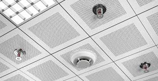
A sprinkler system consists of a series of heads that are connected to a system of pipes, which are usually installed on the ceiling, although they can be installed on walls as well. Pipes are generally made out of fire-resistant plastic, steel, or copper. Depending on the system type, the pipes can be filled with water, pressurized air, or nitrogen gas.
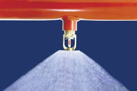
How Sprinklers Work:
A fire sprinkler system are a network of fixed water pipes supplied by two water sources with sprinkler heads fitted at recommended distances apart. Water can be supplied from a tank via pumps or from the town mains, providing the flow is sufficient and fills the pipes.
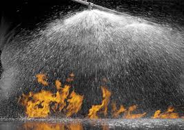
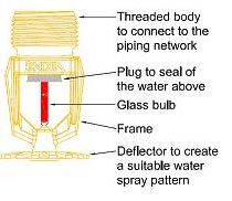
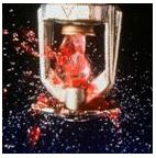
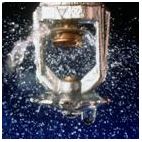
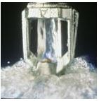
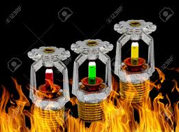
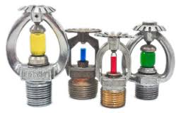
Detector heads are nozzles that direct a jet of water on to a deflector plate which defuses over a large area. The water is held back by a glass bulb or soldered strut which holds a plug in place. When heat is applied from a fire below, the glass bulb will burst, due to expansion of the liquid in the bulb, or the solder will melt, which then releases the plug and water flows through the sprinkler head.
The hot gases from a fire will raise the temperature at ceiling level and when the area adjacent to the head reaches a specific temperature that sprinkler head will actuate and spray water on to a fire. Only the sprinklers over the fire will open and the others will remain closed. This limits any damage to areas where there is no fire and reduces the amount of water needed.
Sprinkler heads can be placed in enclosed roof spaces and into floor ducts to protect areas where a fire can start without being noticed. In a large warehouse sprinklers may be placed in the storage racks as well as the roof.
At the point where the water enters the sprinkler system there is a valve. This can be used to shut off the system for maintenance. For safety reasons it is kept locked open and only authorized persons should be able to close it.
A pelton wheel rotates when water starts flowing in the system which in turn operates a warning bell. This way the sprinkler system both controls the fire and gives an alarm using water, not electricity. Main water shut off valve which allows the system to be closed down when the fire has been extinguished.
Types of Fire sprinkler Systems
Common Fire sprinkler Systems:
Wet Fire Sprinkler Systems:
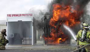
The wet-pipe system employs automatic sprinklers attached to a piping system connected to a water supply. The water discharges immediately from sprinklers opened by a fire. Only those sprinklers which have been operated by heat over the fire will discharge water.
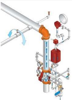
Dry Pipe Systems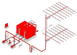
The dry-pipe system employs automatic sprinklers attached to a piping system containing air or nitrogen under pressure. When released, the water flows into the piping system and discharges only from those sprinklers which have been operated by the fire. Dry-pipe systems are installed in lieu of wet-pipe systems where piping is subject to freezing.
Special Hazard Fire Protection Systems:
Special systems are designed to detect and extinguish fires in locations where standard suppression systems are not appropriate or adequate.
Pre-action Systems:
A sprinkler system employing automatic sprinklers attached to a piping system containing air under pressure with a supplemental detection system installed in the same area as the sprinklers. Operation of the detection system activates tripping devices that open a deluge valve, simultaneously and without loss of air pressure in the system.
Deluge Sprinkler System:
Sprinkler system employing open sprinklers that are attached to a piping system that is connected to a water supply through a valve that is opened by the operation of a detection system installed in the same area as the sprinklers.
Anti-Freeze Sprinkler System:
A wet pipe sprinkler system employing automatic sprinklers that are attached to a piping system, that contains an anti-freeze solution and that are connected to a water supply.
Wet pipe fire sprinkler systems:
The Wet pipe fire sprinkler system contains pressurized water inside the pipes ready for use at all times. The second type of fire sprinkler system issues water by demand. Damage to property by water from fire sprinklers or from a fire sprinkler system is remote compared to the likelihood of widespread damage caused by fire, however fire sprinklers must be maintained to ensure their optimum performance.
The wet sprinkler system can reduce the spread of fire quickly using a either a fire sprinkler system with water by demand, or a pressurized wet fire sprinkler system. Potential for leaks in the wet system from extended periods water pressurization are prevalent as is water stagnation and biological contamination. Heat is necessary to prevent any freezing of the water within the wet fire sprinkler system fin colder climates.
Dry pipe sprinler systems:
A dry pipe installation is a sprinkler installation in which the installation pipe work is permanently charged with gas under pressure above the alarm (dry pipe) valve and with water under pressure below the valve. When a sprinkler head opens, the gas pressure drops allowing the dry pipe valve to open and admit water to the installation. To speed up the opening of the valve an accelerator or exhauster may be included in the installation.
Dry pipe installations are only permitted for installations where freezing of water in the pipes would be a problem (e.g. cold and cool stores or areas where climatic conditions may cause freezing) or in areas where the ambient temperature is above 70°C (e.g. drying ovens).
Dry pipe sprinkler installations must be carefully designed to ensure that the discharge of water onto a fire is not unduly delayed in order to ensure that effective fire control is achieved. Argus Fire Protection’s design and engineering team are able to tailor the design of these systems to ensure that your specific needs are met and compliance with the relevant codes and standards is achieved.
Pre-action Sprinkler System:
Pre-action sprinkler systems are utilized in situations where a greater level of security against false discharge of water is required.
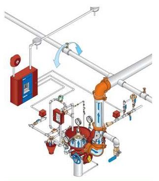
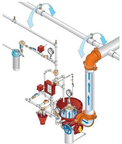
Schematic of a pneumatically pre-action system.
A pre-action sprinkler system is a form of dry pipe sprinkler system incorporating water discharge pipework fitted with closed sprinkler heads, but charged with low pressure gas for supervision purposes. Water entry to this piping system is controlled by an independent detection system, usually either electric (e.g. heat detectors, smoke detectors, or other detectors suited to the specific risk being protected) or a further system of small diameter piping with closed sprinkler heads charged with gas for control purposes.
Before water may be discharged it is necessary that both the detection system and the sprinkler heads on the discharge pipework operate.
Pre-action sprinkler systems are categorized by their style of operation (generally either single interlock or double interlock) and their type of detection (generally electric or pneumatic) as described below.
Types of Pre-action Sprinkler Systems
The basic types of pre-action sprinkler systems and their typical uses are described below.
Single Interlocked:
With a single interlocked pre-action sprinkler system the pre-action control valve opens and charges the discharge pipework with water on operation of the detection system. Water is not discharged from the discharge pipework until one of the closed head sprinklers on the discharge pipework operates.
The discharge pipework is normally charged with gas at low pressure for supervision purposes to ensure that the pipe remains closed. If a sprinkler on the discharge pipework is operated without the detection system operating then the pre-action system will provide indication of a defect state, so that the service agent can be brought to site to repair the system.
Single interlock pre–action systems are typically installed to protect sensitive equipment such as computer server suites which require a higher level of protection against accidental water discharge.
Double Interlocked:
With a double interlocked pre-action sprinkler system the pre-action control valve does not open until both the detection system and one of the closed head sprinklers on the discharge pipework operates.
Double interlocked pre-action sprinkler systems are more complex than single interlocked sprinkler systems and are therefore considered to be less reliable. In addition because the pre-action control valve does not open until both the detection system and a closed head sprinklers on the discharge pipework operate there is a longer delay before water is discharged onto the fire.
Pneumatic Detection: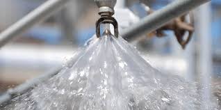
The most common type of detection for a pre-action sprinkler system is pneumatic detection where a system of small diameter piping with closed sprinkler heads charged with gas (normally dry air) is distributed throughout the enclosure for detection and control purposes. When a sprinkler on the detection network operates, the gas pressure is lost and the pre-action control valve operates.
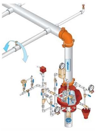
Deluge and Water Spray Systems:
Deluge systems are installations with a discharge pipe array fitted with open sprinkler heads or water spray nozzles with the water to the discharge pipe array being controlled by a quick opening (deluge) valve.
The operation of the deluge valve is controlled by an independent detection system, usually either electric (e.g. heat detectors, smoke detectors, or other detectors suited to the specific risk being protected) or a further system of small diameter piping with closed sprinkler heads charged with gas or water for control purposes.
Schematic of a pneumatically activated deluge system.
On operation of the detection system the deluge valve is opened, water is admitted into the discharge pipe array and is discharged through the open sprinklers or water spray nozzles to provide complete coverage of the entire protected area.
Deluge systems are designed primarily for the protection of high hazard risks where intensive fires with a rapid rate of propagation are expected and it is desirable to discharge water simultaneously over the entire zone in which the fire may occur.
Water spray systems are utilized for more challenging fires where it is necessary to direct the water onto the hazard or surface being protected using directional nozzles. Water spray systems are most commonly used for exposure protection of bulk storage flammable and combustible liquid tanks to cool the shell, prevent explosion or collapse of the tank and extension of the fire. In addition, water spray systems can be utilized for extinguishable and control of some flammable liquids fires, some combustible liquid fires, class A combustibles, and electrical transformer applications.
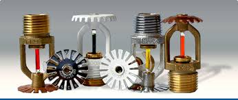
Sprinkler Head Types: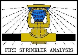
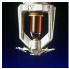
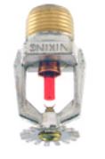
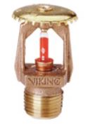
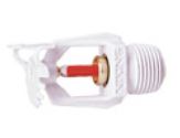
Spray sprinklers are manufactured in three basic styles. A standard spray upright (SSU) sprinkler is mounted on upright above a branch line pipe, usually in a room with exposed structural elements, and has a deflector, a metal plate whose edge is distinctively bent to deflect water downward from the sprinkler. A standard spray pendant (SSP) sprinkler is mounted below the branch line, usually mounted at or below the surface of a suspended ceiling and is characterized by a flat deflector. SSU and SSP discharge patterns are designed to be the same. Sidewall sprinklers have a specifically designed deflector that allows the sprinkler to discharge water from a wall-mounted position.
Variations on upright, pendant, and sidewall sprinkler are the dry upright, dry pendant, and dry sidewall sprinklers. These special sprinklers are manufactured with a seal at the inlet that prevents water from entering the nipple until the sprinkler actuates. These sprinklers can be extended from a wet pipe system into an unheated area, such as a walk-in freezer, an outside loading dock, or an unheated attic space, or can be used in the pendant position on a dry pipe system to prevent condensation from entering the sprinkler and freezing.

Sprinkler Coverage:
Another development in sprinkler manufacturing is the extended coverage sprinkler. The deflectors on these sprinklers are designed to discharge water over larger areas than standard sprinklers. While this means that each sprinkler must have a higher flow, it results in increased allowable distance between sprinklers, with the possibility that fewer sprinklers may be required in a compartment given size.
Sprinkler Responses: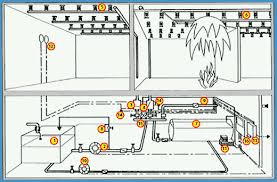
A major development in sprinkler technology was the quick response sprinkler, a sprinkler with specially designed response element that allows the rapid transfer of heat to the heat-responsive element and provides a more expeditious delivery of water to the fire. At the time of sprinkler actuation, the fire should be smaller with a quick response sprinkler than with a standard response sprinkler, resulting in fewer sprinklers likely to actuate. Sprinkler elements are either glass bulbs or eutectic (soldered) elements.
The response of quick response and standard response sprinklers can be modeled by designers to estimate the time for a sprinkler to actuate, given ceiling height, fire size, and response time index (RTI), using the DETACT computer program,developed by the Building and Fire Research Laboratory at the National Institute of Standards and Technology (NIST). Response time index is a measure of the sensitivity of a sprinkler heat responsive element, with low RTI values being very sensitive to actuation by heat, and high RTI values being less sensitive.
Sprinkler Head Temperature Ratings:
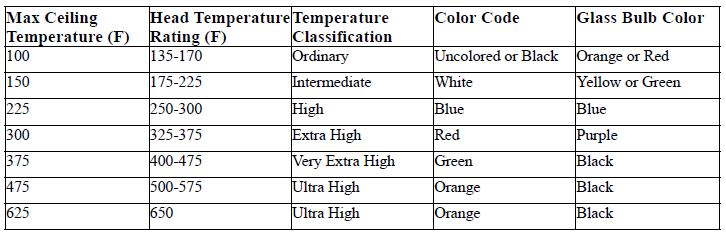
Sprinkler for Storage Applications:
Large Drop sprinklers are for specialized high challenge fire hazards. An sprinkler has a quick response element and an extra large orifice that allows for greater amounts of water to be applied early in the fire development, usually on a high challenge fire. Large drop sprinklers have large deflectors with widely spaced teeth to facilitate the creation of large water drops intended to penetrate a high velocity fire plume without evaporating, resulting in some water reaching the burning materials. The fire plume is the column of smoke and gas traveling upward from a fire.
Sprinkler System Inspection Requirements: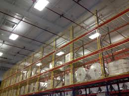
NFPA requires that certain activities be performed at prescribed frequencies. However, rarely does an inspection and test agreement assign all of these activities and frequencies to a fire prevention company. To comply fully, an implied partnership is formed between the owner or the ownerʼs representative and the contractor. All of the requirements of NFPA 25 are the responsibility of the owner, and the contractor relies on the owner to perform all inspections and tests not specified in the agreement.
Unless specifically referenced in the agreement all other less-frequent activities are not included such as testing gauges every 5 years, testing sprinklers every 5, 10, 20, or 50 years; and internally inspecting alarm valve, check valves, strainers, filters, and orifices. These activities are normally performed by the fire protection contractor but are invoiced as additional periodic services.
Zoning:
It is important for sprinkler designers and fire alarm designers to work together in buildings of any size or complexity. The fire alarm system will often have an annunciation to indicate the location of the alarm to the fire service. Coordination is essential to furnish the fire service with clear information on the fire or its location.
The sprinkler piping arrangement will determine how specific a fire alarm annunciator is able to indicate water flow signals. In other than very small buildings, a separate sprinkler zone should be provided for each floor level. This will allow the fire alarm annunciation to indicate the floor level, directing the firefighters to the correct floor.
As the size of each floor increases, the amount of time it takes firefighters to search a floor to find the fire location increases. Large floor levels should be divided into zones (figure 8.2).
This accomplishes two things:
(1) it allows the fire alarm to indicate the fire location more specifically within a floor, and
(2) it limits the system area taken out of service for maintenance, repairs, or renovations.
Sprinkler designers should consider firefighter access when arranging zones. As a case in point, consider an apartment building in which some individual apartments span two stories (figure 8.3). If the two-story units can only be accessed from one level, the sprinklers in both levels of those units should be zoned with the level of entry.
In buildings with standpipe systems, sprinkler systems are usually combined with them and fed by a single water supply. Typically, all sprinklers would be located downstream from a zone control valve that will shut off water to all sprinklers but not to fire hose connections. This allows the hose connections to remain available for manual fire suppression during times when one or more sprinkler zones are shut off for any reason, either before or during an emergency incident.
Control Valves:
Valves that control sprinkler systems or specific zones must normally remain open. Codes often require them to be supervised electrically by the fire alarm system or another method. Electronic supervision can help ensure that valves are returned to the open position after repair or maintenance.
Fire service personnel often need rapid access to water supply control valves. If a valve is closed when an incident occurs, it may need to be opened to permit the flow of water. Conversely, a sprinkler valve may need to be closed to assist in manual suppression efforts. At the conclusion of an incident, valves are turned off as quickly as possible to limit water damage. This also allows the fire service units to return to service as soon as possible to be available for other responses. Accordingly, careful consideration should be given to access, signage and proper pre incident planning.
Valves can be installed for a variety of purposes, including main shutoff, zone (sectional) shutoff, fire pump bypass, pump testing, draining, and testing. Control valves are not installed in fire department connection (FDC) feed lines; this ensures that this important backup to the primary water source can never be shut down easily or inadvertently.
Labeling each valve clearly to indicate its purpose avoids confusion. This can be helpful during an emergency incident and during repair or maintenance, when a valve can inadvertently be shut off or left shut. Using descriptive labels such as “sprinkler system 12th floor” or “pump bypass — normally closed” are far better than simply “control valve.” Some jurisdictions also require color coding of valves or valve handles.
Glossary of Terms:
Back flow Prevented: Check valve that will close at zero flow.
Back flow Prevention: Arrangement of pipe and fittings designed to prevent reverse flow and back siphoning of potential contaminants into the water supply.
Check Meter: Meter installed by the Water Company to monitor potential illegal usage, no standing or volumetric charge is made unless there is usage for purposes other than fire related.
Check Valve: Device to ensure that water only flows in the single intended direction in a pipe.
Cistern: Water Storage vessel with a water surface exposed to atmospheric pressure.
Communication Pipe: The section of service pipe owned and maintained by the Water Undertaker.
Downstream: In the direction of normal flow of the water in a pipe
Priority Demand Valve: Device automatically operated by control system to isolate the flow to the domestic system in the event of a fire, thus ensuring all available pressure and flow is directed to the sprinkler system.
Pump and Tank Supply: Supply of water from a storage cistern via a booster pump to ensure adequate pressure and flow to meet sprinkler system requirements.
Service Pipe: The branch from a water main to the first internal stop valve intended to provide a supply of water to a specific customer or group of customers.
Sprinkler Head: The outlet fitting from which water is discharged in a spray pattern to control fires.
Sprinkler System: The assembly of pipes fittings and valves to distribute water under pressure to sprinkler heads.
Stop Valve: Device to isolate the supply of water. Also referred to as a “stop tap.”
Supply Pipe: The Section of service pipe owned and maintained by the customer.
Upstream: In the direction opposite to the normal flow of water flow in a pipe.