Power transmission guards:
Power transmission parts typically consist of belts, pulleys, chains, sprockets, gears, shafts, and couplings. Contact with these moving parts accounts for a large number of preventable injuries. It is usually a straightforward task to fabricate and install guards for these hazards.
Refer to “Design and performance requirements for barrier guards” (Part-1) for the do’s and don’ts associated with barrier guards. Two very common machine guards are:
V-belt/chain-sprocket guard
PTO (power take-off) drive shaft guard (frequently found in agriculture)
V-belt/chain-sprocket guard(Fig4.1)
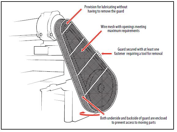
Figure 4.1. Typical fabrication design of the V-belt/chain-sprocket guard.
PTO drive shaft guard
Unguarded PTO (power take-off) drive shafts account for a large number of serious entanglement injuries, especially in agriculture, where they are frequently used with tractors for powering portable machinery such as irrigation pumps. Because the equipment is powered for frequent, short periods there is a tendency to neglect installing guards over these drives. It is a good practice to install a chain or cable tether at each end of the PTO drive shaft guard so that the guard can be readily secured to the tractor or portable equipment when not in use.
Fig-4.2
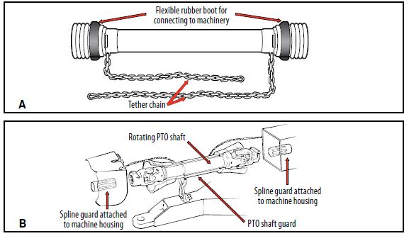
Figure 4.2. PTO drive shaft guards. (A) With tether chain attached to each end of the guard. (B) Cutaway view of PTO drive shaft and typical guard.
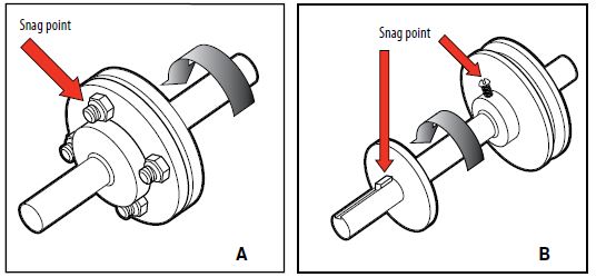
Rotating shaft and coupling guard:
Fig-4.3
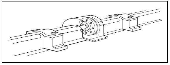
Figure 4.3. Typical design of a rotating shaft and coupling guard.
Conveyors
This section focuses on two common types of conveyors:
Belt conveyors
Screw (auger) conveyors
Belt conveyors
Injuries associated with unguarded belt conveyors generally involve one of two moving parts:
- The power transmission drive (V-belt or chain-sprocket drive and transmission)
- The conveyor belt itself where it engages around the head or tail spool (also known as the drum)
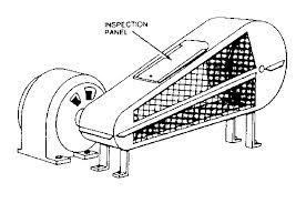
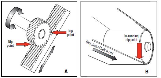
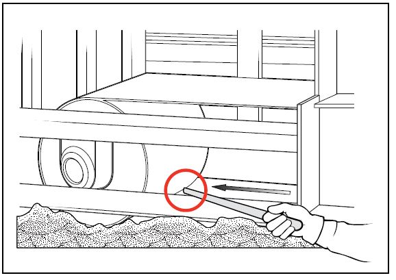
Guarding of the power transmission drive is done using the safeguarding methods described earlier for typical power transmission drives. Guarding of the in-running nip point between the running belt and the head or tail spool is achieved by fully enclosing access to the belt and spool for a minimum of 1 metre (3.3 feet) back from the centreline of the spool. In industry, this is often referred to as a “boot.” Figure 4.4B shows a typical belt conveyor tail spool boot. The boot must be designed and fabricated to permit tracking adjustments, which must be done when the belt is moving, to be performed without removing the boot.
Where access to the running conveyor belt is not prevented by guardrails or enclosure, a typical safeguarding device consists of an emergency trip wire running the entire length of the conveyor. This safety device must be installed using the safety criteria described under “Grab wire and pull wire devices” .
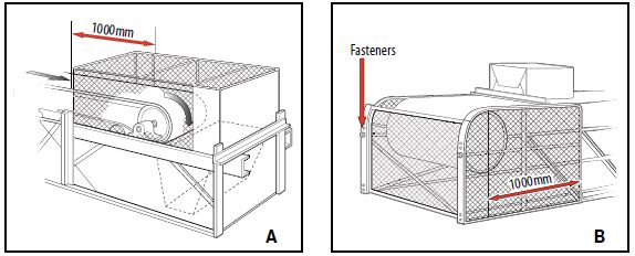
Figure 4.4. Typical belt conveyor boot guards. (A) Head spool guard. (B) Tail spool guard.
Screw (auger) conveyors
Screw conveyors are found in a wide variety of industrial operations,including ice houses, cement plants, pulp mills, grain and feed establishments, and farms. Injuries associated with unguarded screw (auger) conveyors are usually traumatic and extensive, and often result in fatalities from whole-body entrapment. Think of a screw conveyor as a large meat grinder. It is one of the least forgiving types of powered machinery. As with belt conveyors, there are two main sources of harmful engagement:
- The power transmission drive (V-belt or chain-sprocket drive and associated power reduction unit)
- The rotating auger (also known as the vane), which runs through a trough to move the material.
The power transmission drive is guarded using the methods described for typical power transmission drives (beginning on page). The auger itself is typically guarded using solid metal covers if no access to the trough is required during operation. When material must be fed into the running auger, such as those located at floor level in ice houses, guarding material such as grating or horizontal members are often used.
The following safety measures must be built into the guard design:
The openings in the guard are small enough to prevent a hand, arm, or foot from engaging the running auger (see “Power transmission guards and enclosures: maximum permissible openings”).
The guards are securely bolted in place using fasteners that require a tool for removal. Quick-release latches are not permitted.
Figure 4.5 shows a point-of-operation feed guard for an ice auger located at floor level. Because a worker is present at all times to tend the operation to ensure a flow of ice in the conveyor, the guards may be designed to allow ice to be shoveled onto the conveyor but must prevent any part of the worker’s body from touching the moving auger.
Figure 4.5. Ice auger conveyor with good functional design.located at floor level. Because a worker is present at all times to tend the operation to ensure a flow of ice in the conveyor, the guards may be designed to allow ice to be shoveled onto the conveyor but must prevent any part of the worker’s body from touching the moving auger.
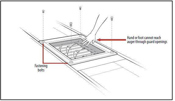
Figure 4.5. Ice auger conveyor with good functional design.
Safe work practices for conveyors:
1. Don’t perform service on a conveyor until the motor disconnect is locked out.
2. Service a conveyor with authorized maintenance personnel only.
3. Keep clothing, fingers, hair, and other parts of the body away from the conveyor.
4. Don’t climb, step, sit, or ride on the conveyor at any time.
5. Don’t load the conveyor outside of the design limits.
6. Don’t remove or alter conveyor guards or safety devices.
7. Know the location and function of all stop/start controls.
8. Keep all stop/start control devices free of obstructions.
9. All personnel must be clear of the conveyor before the conveyor isstarted.
10. Operate the conveyor with trained personnel only.
11. Keep the area around conveyors clear of obstructions.
12. Report all unsafe practices to your supervisor.
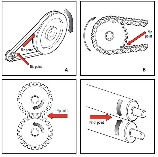
Accidents around conveyors occur most frequently due to:
- Unguarded power transmission parts
- Unguarded nip points
- Unguarded shear points
- Unguarded pinch points
- Unguarded spill points
- Un barricaded access to areas under counterweights
- Tension take-up points
- Transfer mechanisms
- Absence of safe passage under conveyors
Feed rolls
Safeguarding feed rolls in general
Feed rolls are found in a wide variety of industries, such as paper products manufacturing and sheet metal production. They present a high risk of serious injury because of their high speed of operation.
Once a worker is caught in a feed roll, the damage is done quickly, and stopping the equipment will not undo it.
In general, there are two types of feed rolls:
- Those that run material into a machine but do not have to be accessed by workers. These can usually be safeguarded by enclosure or location within the machine.
- Those that are hand-fed as part of the production process. These require closer attention to safeguarding.
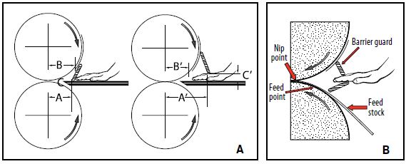
Safeguarding design criteria for feed rolls fed by hand Figure 4.6 provides guidance for designing fixed barrier guards to prevent hands from accessing the nip points created by feed rolls.
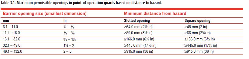
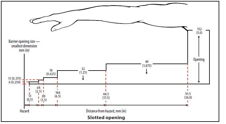
Please refer to “Point-of-operation (feed) guards: maximum permissible openings” beginning on for the safe distances for guard placement and guard openings.
You can also use the following rule of thumb to determine the maximum safe opening in a feed guard located less than 305 mm (12 inches) from the danger zone:
- Maximum safe opening = 6 mm (¼ inch) + 8 of the distance from the guard to the point where the rolls are 9 mm (a inch) apart (the danger zone)
You may have to make a sketch to determine this distance.
Example
A guard is needed for an operator feeding sheet goods into feed rolls 152 mm (6 inches) in diameter and 9 mm (a inch) apart. The guard must be within 102 mm (4 inches) of the centreline of the rolls in order to accommodate the type of material being fed.
How large a feed opening can be allowed under the guard?
Solution
The feed rolls meet at 9 mm (a inch) apart. The distance from thedanger zone (in this case, the centreline of the rolls) to the guard is therefore 102 mm (4 inches). The maximum permitted opening is: 6 mm (¼ inch) + 8 of 102 mm (4 inches) = 6 mm (¼ inch) + 12 mm (½ inch) = 18 mm (¾ inch)
Metal-forming equipment
Punch presses
Types of punch presses A punch press is a machine used for piercing holes or other openings in sheet metal or plate. The tooling or die set consists of two parts: the upper male punch and the lower female die. The punch is fitted to a ram or slide, which moves down and up by mechanical, hydraulic, or pneumatic power. The punch pierces the material and enters the lower die. A punch press can be small and manually operated and hold one punch and die, or be very large and CNC (Computer Numerical Control)-operated, and hold many punches and dies of various sizes and shapes.
Punch presses are manufactured in many shapes and sizes, ranging from 2-ton benchtop models to 500-ton floor models and larger. The tonnage of a punch presses refers to the total force between the dies. In an oversimplified example, a 100-ton punch press with a 25.4 cm (10 inch) × 25.4 cm (10 inch) die area (645 cm2 [100 square inches]) will achieve a force of 13,800 kilopascals (1 ton per square inch).
A press that must complete one full revolution before the stroke can be stopped is called full revolution clutch. A press equipped with an air-friction clutch, and with a proper control package, is capable of being safely stopped anywhere during its stroke. This type of press is called part revolution clutch. The difference is important because it will dictate the types of safeguards that can be used.
Presses can be further classified by the type of power source: mechanical (electrical motor and flywheel for energy transfer to the crankshaft) or hydraulic.
Figure 4.7 shows the two most common punch presses found in general use.
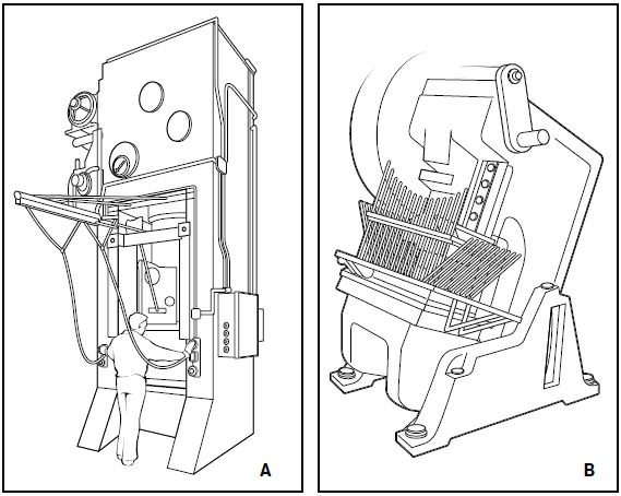
Figure 4.7. Most common punch presses in general use. (A) Straight side hydraulic power press (no flywheel) – press remains in vertical position. (B) OBI (open back inclinable) mechanical punch press – press can be tilted back to allow formed parts to drop out of the back.
Methods of safeguarding
The two critical areas of safety on punch presses are:
- Point-of-operation (feed point) safeguarding
- Control reliability (can the machine come to a safe stop consistently and reliably in the event of an unsafe condition or when an emergency stop signal is given?)
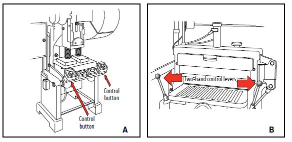
Because a punch press can be used for many different operations (hand feeding, automatic strip/coil feeding, and so on) there are several effective ways to safeguard the point of operation. Figure 4.8 shows the many options available.
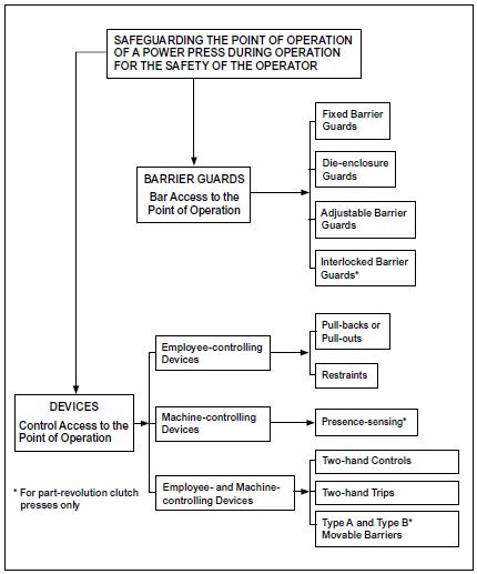
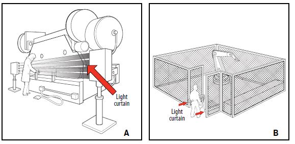
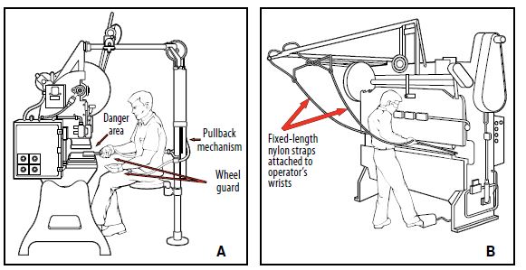
Figure 4.8. Safeguarding options for punch and brake presses.
Brake presses
Types of brake presses
Whereas punch presses are generally used for piercing metal, brake presses are used mostly for bending sheet or plate metal. Brake presses are generally rated by the length of the press bed. The longer the bend, the longer the piece that can be inserted into the dies. Each cycle of a brake press is called a stroke.
Brake presses are normally fed by hand and operated with a foot control, which places them at high risk for amputations. Brake presses have part revolution clutch operation; if the foot treadle or electrical control is released, the ram (the part that holds the upper die and moves down and up) either stops or returns to top of stroke.
Brake presses are also classified by the type of power source:
- Mechanical (electrical motor and flywheel for energy transfer to the crankshaft)
- Hydraulic
- Hydro-mechanical (a combination of mechanical actuation with hydraulic assist)
Methods of safeguarding:
The two critical areas of safety on brake presses are:
- Point-of-operation (feed point) safeguarding
- Control reliability (can the machine come to a safe stop consistently and reliably in the event of an unsafe condition or when an emergency stop signal is given?)
The options for safeguarding the point of operation of a brake press are somewhat limited. This is because the profile of the formed piece is substantially different after the bending process. What goes into a narrow die space as flat stock may have to be removed as a complex shape, so brake press operations generally require a fair amount of open space between the dies. The exception to this would be smallpiece parts that can be fed into an open die space of 6 mm (¼ inch) or less (safeguarded by minimum opening) and removed without difficulty. Additional safeguarding is required at the ends of the press.
Besides point-of-operation safeguarding, an awareness barrier, usually in the form of a chain or rope with appropriate signage, should be installed across the back of the brake press to deter access by unqualified persons.
Point-of-operation safeguarding is generally limited to three options:
- Light curtain devices that are mounted at either end of the press bed and detect entry of a hand or body part into the die space. These devices can be programmed to recognize the varying profiles of piece parts and selectively mute or blank out the light beam channel(s) that may interfere with the proper functioning of the light curtain. These devices offer the least interference with normal press operation. They are particularly well suited to hydraulic brake presses. If they are retro-installed on a mechanical brake press, modifications will have to be made to the existing brake and clutch system, and a control-reliable package will have to be installed.
- Two-hand controls coupled with foot switch operation. This type of conversion package uses control-reliable components to enable the operator to bring the ram down to a 6 mm (¼ inch) or less closure using two-hand controls, then change over to foot control operation. The foot control is inoperative during the initial part of the downstroke. This method normally requires the piece part to be supported for productive operation.
- Pull-back or restraint devices. Although not commonly used, they might be considered for some dedicated brake press operations with infrequent die and piece part changes.
Power shears (sheet metal and plate):
The two critical points of operation on a guillotine shear are:
- The blade, which does the actual cutting
- The hold-down clamps or “feet,” which hold the work piece in position during the cutting cycle
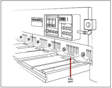
The hazards posed by the blade and clamps are hidden by the guard (Figure 4.9).
Methods of safeguarding:
Three type of safeguards are used to protect the point of operation of shears:
- A fixed barrier guard designed with openings large enough to allow the flat stock into the shear but small enough to keep fingers out.
- A fixed barrier guard with an awareness modification that allows larger thicknesses of plate steel (greater than 12 mm [½ inch]) to enter the shear but warns the operator that his or her fingers are approaching the danger area.
- Two-hand controls, which are not common but are found in some specialized cut-to-length operations
Besides point-of-operation safeguarding, an awareness barrier, usually in the form of a chain or rope with appropriate signage, should be installed across the back of the shear to deter access by unqualified persons.
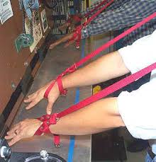
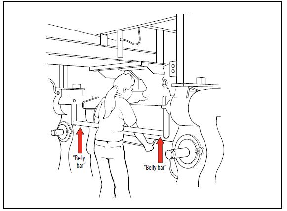
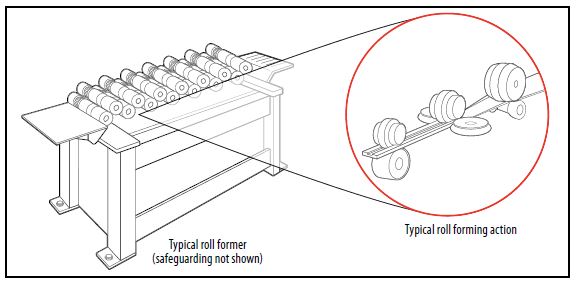
Hand-fed powered metal-forming rolls:
Steel fabrication shops make use of equipment for rolling sheet metal or plate into cylinders. These metal-forming machines are often referred to as “pyramid rolls” or “initial pinch offset rolls” (Figure 4.10). They present a unique safeguarding challenge: the point of operation must remain accessible during the entire forming operation. This exposes both the operator and helper to the risk of being drawn into the powered rolls. Safeguarding usually consists of an emergency body contact device such as cable wire or a bumper bar (see “Miscellaneous emergency body contact devices” on page 40) that will be involuntarily activated by the operator or helper in case of entrapment in the rollers.
Because the rolls are under very high operating pressure, the equipment will normally come to a very sudden stop when the emergency stop device is activated. It is important that this device be installed so that both the operator and the helper can access it.
Abrasive equipment:
An abrasive tool uses an abrasive wheel to wear away the surface of a workpiece to change its shape. An abrasive wheel consists of a bonded abrasive material with properties specific to the material being worked; for example, a wheel intended for ferrous material may not be suitable for grinding nonferrous material.
There are three common types of grinding machines:
- bench grinders,
- pedestal grinders, and
- portable grinders.
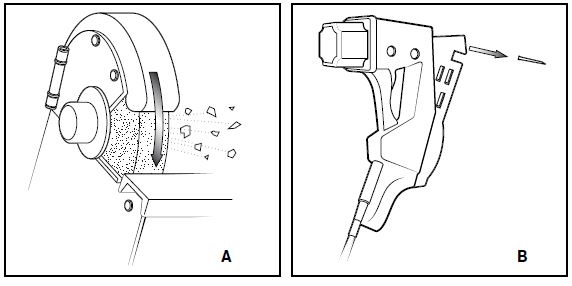
The greatest risk associated with abrasive equipment is fragmentation of an abrasive wheel. The size and peripheral speed of the wheel determine the amount of energy that will be released in the event of a failure. The main objective of safeguarding is to contain pieces of the abrasive wheel if a rupture occurs.
There are two important areas where training and safeguarding will prevent serious injury and death:
- Proper storage and handling of abrasive wheels
- Appropriate safeguarding of stationary and portable grinders
Proper storage and handling of abrasive wheels Wheels (especially vitrified or glass-based wheels) are easily damaged if they are bumped or dropped. That is why it is so important to store and handle them carefully.
- Check all wheels when you receive them and before using them.
- Follow the manufacturer’s instructions for storage. Proper sorting and storage of grinding wheels will help ensure easy access, less handling, and less chance of error.
- Store grinding wheels in an area that is dry and protected against damage from impact, solvents,high humidity, and extreme heat or cold.
- Store portable grinders on hooks or in V-shaped racks. Protect racks from damage.
- Arrange grinding wheels so that older ones will be chosen before newer ones.
- Never roll a wheel on its edge; it may absorb oil or dirt from the floor, and get damaged.
Design criteria for abrasive wheel guards:
Figure 4.11 illustrates the maximum wheel exposures for guards on two types of abrasive equipment: bench and pedestal grinders (90° exposure) and hand-held angle grinders (180° exposure). When a portable grinder is being used for grinding root passes in welded pipe, the protective hood must cover at least 120° of the wheel periphery and the operator must wear adequate eye and face protection.
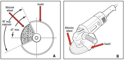
Figure 4.11. Maximum wheel exposures for different types of abrasive wheel guards.
Safe work procedures for bench and pedestal grinders:
- Pedestal grinders must be securely attached to the floor. Benchgrinders should be securely fastened to a bench.
- Always check that the rated RPM (revolutions per minute) of the grinding wheel is consistent with the rotational speed of the grinding machine.
- Always wear eye protection (safety glasses or impact-rated face shield).
- Never remove wheel guards from a bench/pedestal grinder. They offer protection in case of wheel failure, and protect hands and fingers from injury.
- Work rests or tools rests must be provided on all machines. The work rest must be securely fixed and adjusted close to the grinding wheel (maximum distance of 3 mm [8 inch]). It should be adjusted as the disc becomes smaller through wear and dressing. Never adjust tool rests while the grinder is running.
- Before commencing grinding, allow the grinding wheel to run at operating speed for at least one minute. Do not stand directly in front of a grinding wheel when it is first started. Do not use a wheel that vibrates.
Woodworking equipment:
Equipment and machinery used in woodworking are dangerous when used improperly or without proper safeguards. The most common injuries to workers are lacerations, amputations of the fingers and hands, and loss of sight. Besides traumatic injuries, workers in this industry can suffer from skin and respiratory diseases from exposure to wood dust and the chemicals used in finishing.
This section describes the principal hazards of woodworking equipment and some methods for controlling these hazards through safeguarding. It is not a substitute for a thorough knowledge of the Occupational Health and Safety Regulation. This section does not cover machinery used in the primary production of lumber and basic wood materials at sawmills and lumber remanufacturing plants.
Safety and health hazards:
The main occupational hazards associated with woodworking operations are as follows.
Safety hazards:
- Machine hazards (point of operation, power transmission components)
- Kickbacks
- Flying chips and material
- Tool projectiles (unbalanced cutter heads)
- Fire and explosion
- Electrical
Health hazards
- Chemical (sensitization from exposure to finishes, coatings,
- adhesives, solvents)
- Wood dust (some are carcinogens)
- Noise
- Vibration
Safeguarding commonly used on woodworking machines:
The following are recommended point-of-operation safeguarding techniques and safe work practices for several machines commonly used in the woodworking industry. Personal protective equipment is not specifically covered because its use applies to all industrial machinery. Work practices that apply to all woodworking equipment (such as using a brush for cleaning saws) are not covered either.
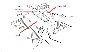
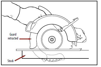
Figure 4.12. Typical table saw.
Radial arm saw
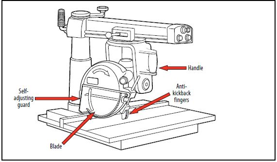
Figure 4.13. Typical radial arm saw.
Use and operation:
Radial arm saws are circular saws that rotate downward either with (rip) or against (crosscut) the wood grain. For crosscutting, the wood is placed against a fence away from the operator and the blade is pulled into the stock. For rip cuts, the blade is set parallel to the fence and the
stock is pushed through.
Radial arm saws have features that make them more versatile than table saws. The saw arm can be raised and lowered and swung to the side to adjust the depth and horizontal angle of the cut. The blade can be replaced with shaping cutters, disk or drum sanders, or other accessories.
Recommended safe work practices:
- During crosscutting, operate the saw on the side of the table with the handle.
- During ripping, make sure the stock is fed in the correct direction to avoid serious kickback hazard.
- Clearly mark the direction of saw rotation on the protective hood (guard).
- Measure boards using an end stop gauge. If measuring by rule, turn off the saw. Wait for the blade to stop before making measurements.
- Before performing angular cuts, check the intended direction of the saw blade (for example, compound 45° cuts).
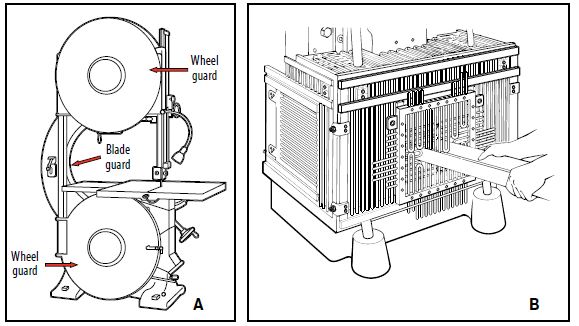
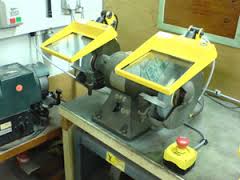
Band saw:
Figure 4.14. Typical band saw.
Use and operation:
Band saws are used both for straight sawing and for cutting curved pieces. The band saw uses a thin, flexible, continuous steel strip with cutting teeth on one edge. The blade runs on two pulleys, one driven and the other an idler, through a hole in the work table on which stock is fed. The operator hand-feeds and manipulates the stock against the blade to saw along a predetermined line.
Recommended engineering controls
- Guard the blade entirely except at the point of operation (the working portion of the blade between the bottom of the guide rolls and the table).
- Use a self-adjusting guard for the portion of the blade between the sliding guide and the upper saw so that it rises and lowers with the guide.
- Properly adjust the blade guide post to fit the thickness of the stock and to provide additional guarding.
- Fully enclose the band wheels.
- Guard feed rolls if they are used as a method of feeding the saw.
- Consider installing a braking system on one or both wheels to minimize the potential for coasting after the saw has been shut off; otherwise, do not remove material until the blade has stopped.
- Make sure the saw includes a tension control device to indicate proper blade tension.
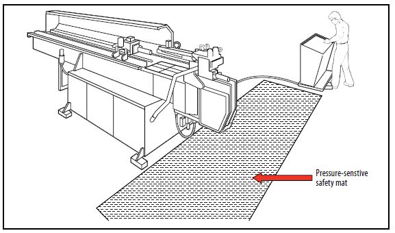
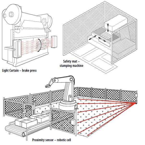
Industrial robots and robotic systems:
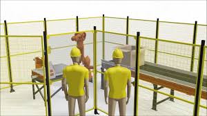
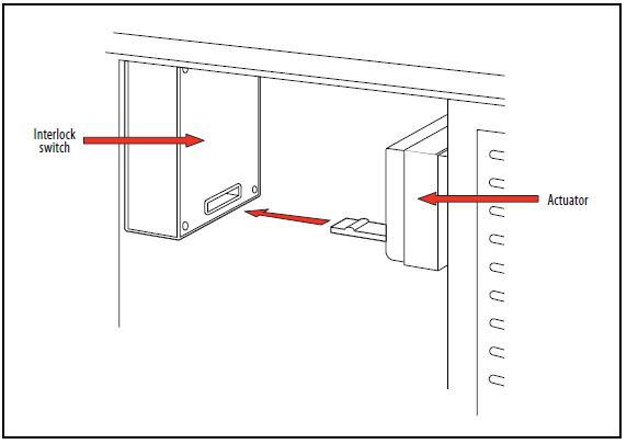
The use of robots and robotic systems in manufacturing has become mainstream in large manufacturing operations such as the automotive industry, and their use in small manufacturing plants and niche operations will increase. Unauthorized entry into the working envelope of a robot exposes a worker to the potential for serious impact or crushing injuries from the unexpected movement of the robot. The safeguarding of robots requires a systems approach to safeguarding. It typically uses a combination of fixed barrier fences, interlocked gates, and presence-sensing devices such as safety mats and light curtain devices. Figure 4.17 shows a typical robot work cell safeguarding system.
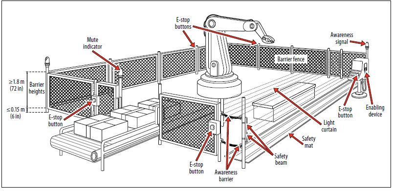
Figure 4.17. Typical robot work cell safeguarding system.

- train all machine operators on proper machine operation and safety procedures.
- inspect machinery before each use-ensuring that safeguarding systems are in place and working properly.
- follow all machine operating and maintenance instructions.
- use appropriate personal protective equipment-such as safety glasses or goggles, respiratory protection and hearing protection.
- keep hands away from all moving parts-at all times.
- exercise good housekeeping. Clean all tools after each use and store them properly.
- keep work area clean and well-lit.
- ensure hazardous energy is isolated and controlled if access to hazardous parts is needed.

- wear loose clothing, jewelry, neckties or other garments and accessories that can become entangled with moving parts on the machine. Long hair must be tied back.
- distract an operator while operating a machine.
- leave machines running without supervision. Turn the power off completely before leaving the work area.
- use your hands to remove material from the machine; use a vacuum cleaner, brush or rake.
- remove, disable, deactivate or try to work around machine guards and safety devices. They’re here to protect you.
- use machines with missing or disabled guards or protective devices
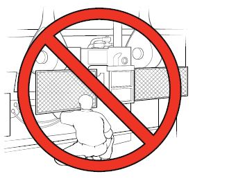
- try to access areas of a machine that have hazardous moving parts while the machine is running.
- use a machine for anything it is not designed to do.
Signage : Machine operations


click the below link to download machine and equipment signage, tool box talk