Over view
There are many rigging methods for different kinds of loads being handled. It should be noted that a rigging method which is suitable for handling one load might not be suitable for handling another load. In fact, each rigging method has its limitations. The methods shown in this section are intended to be typical examples and should not be regarded as exhaustive.
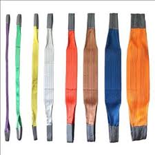
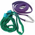
It should be noted that though wire rope slings are used for illustration, the methods shown in this section are also applicable to the use of suitable chain sling.
The owner of any double or multiple sling shall ensure that it is not used in raising or lowering or as a means of suspension if –
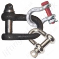
- the upper ends of the sling legs are not connected by means of a shackle, ring or link of adequate strength; or
- the safe working load of any sling leg is exceeded as a result of the angle between the sling legs.
Slings carry their loads in one of three primary sling hitches. Most slings can be used in all three sling hitches, but some slings are designed for use in only one hitch. Slings have the largest work Load Limit when used in a basket hitch.The vertical hitch Work Load Limit is 50% of the basket hitch. The synthetic choker hitch work Load Limit is a maximum of 80% of the vertical hitch work Load Limit.
Slings must be securely attached to the load and rigged in a manner to provide for load control to prevent slipping, sliding and/or loss of the load. A trained, qualified and knowledgeable user must determine the most appropriate method of rigging to help ensure load control and a safe lift.
CHOKER HITCH
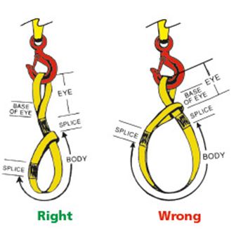
Sling passes through one end around the load, while the other end is placed on the hook. Load control is limited with only one sling rigged in a choker hitch. A choker hitch will never provide full 360 degree contact. For full contact use a Double Wrap Choke Hitch. See Choker Hitches. The Choke Point should always be on the sling body, not on the sling eye, fitting, base of the eye or fitting, splice or tag.
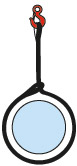
VERTICAL HITCH:
![]()
One end is on the hook, while the other end is attached directly to the load. Use a tagline to prevent load rotation.
BASKET HITCH:
The sling cradles the load while both eyes are attached overhead. As with the choker hitch, more than one sling may be necessary to help ensure load control.
Sling-To-Load Angle:
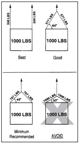
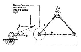
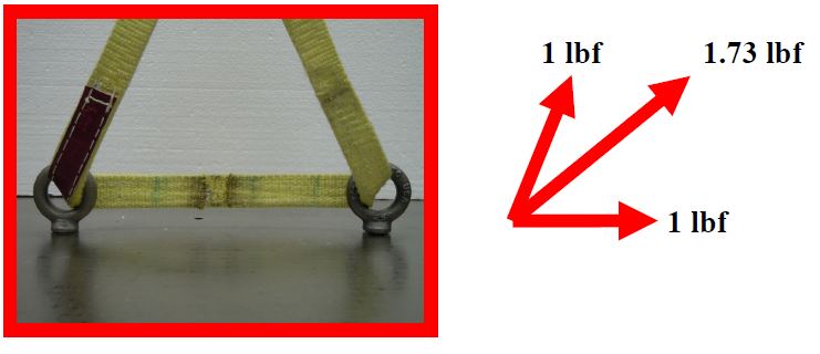
The Sling-to-Load Angle is the angle formed between a horizontal line and the sling leg or body. The Sling-to-Load Angle has a dramatic effect on sling Work Load Limits. Slings with adequate capacity to handle the “scale” weight of the load have catastrophically failed because the Sling-to-Load Angle and increased tension were not taken into account.
This principle applies in a number of conditions, including when one sling is used to lift at an angle and when a basket hitch or multi-leg bridle sling is used. When selecting a sling, always consider the Sling-to-Load Angle and the tension that will be applied to the sling. As the Sling-To-Load Angle decreases, the tension on the sling leg(s) increases.

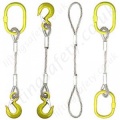
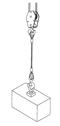
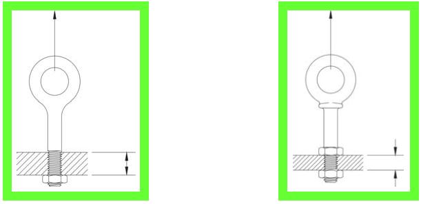
Single-leg sling:
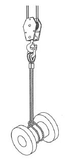
Vertical or straight lift (Fig-1) :
A vertical or straight lift is only suitable for lifting a load that will be stable when suspended from a single lifting point.
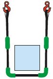
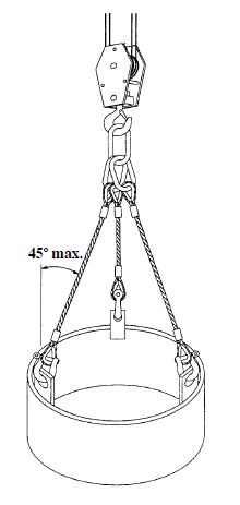
![]() Basket hitch (Fig-2 ):
Basket hitch (Fig-2 ):
A basket hitch should only be used when the sling is passed through part of the load and the load is balanced on the sling. The lifting should not commence until a shackle is connected to the sling legs. The included angle of the sling should not exceed 90 degrees.
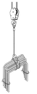
Simple Choker Hitch (Fig-3) and Double and Choked (Fig-4) :
These two slinging methods do not grip the loads completely and should be used only when the loads are easily stabilized or cannot slip out of the sling.
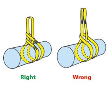
Choker hitch double wrapped (Fig-5) :
The general limitations for this sling method is similar with simple choker hitch, except that with the double wrapped choker hitch the load is gripped more fully, and hence is secured more effectively.
The simple choker hitch or choker hitch double wrapped method should not be used for handling composite loads such as loose bundles of tubes, or bars or wooden battens unless the friction grips between the parts is sufficient to prevent them slipping from the sling. As far as possible, such composite loads should first be tied up securely at their ends by steel wires or similar means of adequate strength.


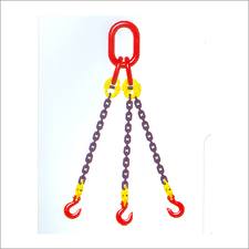
Multi-leg sling:
A multi-leg sling may have two, three or four legs (Fig-6 to 12 ). It provides a more stable lifting arrangement than a single-leg sling.
Generally, multi-leg sling methods are :![]()
- two-leg slings used with direct attachment (Fig. 6);
- two-leg slings used in choker hitch (Fig. 7);
- two-leg slings used in basket hitch (Fig. 8);
- two-leg slings used in double wrap choker hitch (Fig. 9)
- two-leg slings used in double wrap basket hitch (Fig. 10);
- three-leg slings used in direct attachment (Fig. 11); and
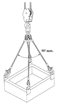
- four-leg slings used with direct attachment (Fig. 12).
When using multi-leg slings, care should be taken to ensure that:
1) the slings are of the same length;
2) where the slings have different safe working load ratings then the load that can be lifted is related to the least safe working load; and
3) the attachment points of a two-leg sling to the load are far enough apart to give stability without exceeding 90 degrees (Fig. 6, 7 & 9). In the case of two-leg sling used in basket hitch or a four-leg sling, the angle between any two diagonally opposite legs should not exceed 90 degrees (Fig. 8, 10 & 12) unless the sling is so marked. In no circumstances should the included angle exceed 120 degrees. For a three-leg sling, any one leg should make an angle of not greater than 45 degrees with the vertical.
The two-leg slings used in choker hitch, basket hitch, double wrap choker hitch and double wrap basket hitch should not be used for handling composite loads such as loose bundles or tubes, bars or wooden battens unless the friction grips between the parts is sufficient to prevent them slipping from sling. As far as possible, such composite loads should first be tied up securely at their ends by steel wires or similar means of adequate strength.


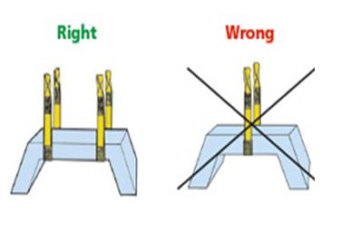
BASKET HITCHES -Right / Wrong:
Inverted basket hitches are referred to as equalizing hitches because the sling is free to slip through the hook based upon the load weight distribution. Be sure to employ the “four ends down”, North to South, load engagement system.
Slings “skipping” through hardware components can become damaged. Balancing the load is critical and necessary to prevent sling damage and failure . Extra care should be taken when using slings in a basket hitch to balance the load to prevent slippage. As with the choker hitch, more than one sling may be necessary to control the load.
As with the choker hitch, more than one sling may be necessary to control the load.If practical, take a full wrap around the load to grip it firmly; be sure when using multiple slings that they do not cross over each other. Wrapping the load is a legitimate method of minimizing excessive sling length. Other methods, such as, twisting and knotting radically reduce sling Work Load Limits. When the load is “wrapped” the sling Work Load Limit is not increased, but load control is.

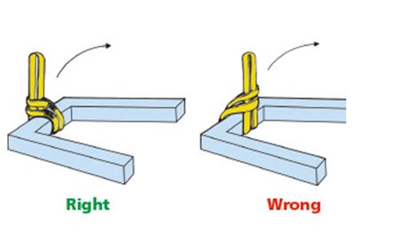
CHOKER HITCHES – Right / Wrong:
The choke hitch should always be pulled tight before the lift is made, not pulled down during the lift. A sling rigged in a choker hitch (not double wrapped) does not make full contact with the load. Use multiple slings to balance the load, and wrap the load to ensure full contact. Ensure multiple slings do not cross. Choke on opposite sides of the load, if this action will not damage the load and maintain load control.
Always use a choker hitch when turning a load. If the sling is not rigged properly, the turning action will loosen the hitch, resulting in load slippage. Place sling eyes on top of the load, pointing the opposite direction of the turn. The body is then passed under the load and through both eyes. Blocking should be used to protect the sling and facilitate removal. Basket hitches should not be used to turn a load. Always downgrade the choker Work Load Limit when the angle of choke is less than 120°.
For a tighter choke hitch, which provides full, 360° contact with the load, take a full wrap around the load before choking the sling. Ensure that multiple slings do not cross. When the load is “wrapped” the sling Work Load Limit does not increase, but load control does.
Double Choker Hitch:
The Double Choker Hitch if applied properly will facilitate equalization of the loading on the sling legs over the lifting hardware. If applied improperly, one of the legs will share a greater portion of the load and equalization will not occur. The Double Choker Hitch Work Load Limit is twice the regular Choker Hitch Work Load Limit.
Sling tension – Different horizontal planes :
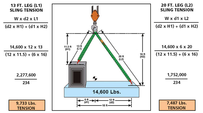
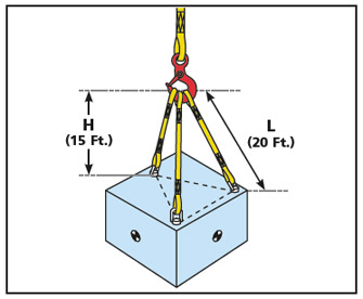
Sling Tension – Leg Length/Headroom:
Calculating the tension imposed on slings or individual legs of a multi-part sling system will enable the sling user to select slings with adequate work Load Limits.
Use the following steps to calculate the tension imposed upon the individual sling legs, when you know the leg Length (L) and Headroom (H).
1)Determine the Load Factor (LAF):
Divide the leg length (L) by the headroom (H)
L ÷ H = LF
Example: 20 ÷ 15 = 1.33 Load Factor (LAF)
2)Determine the Share of the Load (SOL) for the individual sling legs:
Divide the load weight by the number of sling legs.
Load weight ÷ number of legs = Share of the Load (SOL)
Example: 12,000 lbs ÷ 3 legs = 4,000 lbs. (SOL)
3) Multiply Load Factor by the Share of the Load to determine Sling Tension
Load Factor x Share of the Load = Tension
LAF x SOL = Tension
Example: 1.33 x 4,000 = 5,320 lbs.
Please Note: Tension calculations are based upon:
- Sling attachment points being equidistant from the center of gravity
- Sling attachment points being equidistant to each other.
- Sling attachment points being on the same horizontal plane
- Equal sling leg lengths
Planning all Lifts:
Lifting operations must be planned to ensure that lifts are carried out safely and efficiently. The following points must always be considered:
- Where loads are to be picked up
- Where loads are to be placed
- What areas are to be passed over
- Proximity of the public
- Any obstructions in the way
- How the load is to be slung
- How slings are to be removed and access to them
- How the crane driver will be directed
- The weight of the load
- The radius of the lift
- Any loads from a crane or outriggers and the capacity of the ground or slab to support them
- Weather conditions and light.
The Project Health and Safety Plan will record the overall project specific arrangements for the control of lifting operations. The Project Lifting Plan will detail the specific arrangements for lifting.
The Schedule of Common Lifts will define and describe the ‘common lifts’ on the project. Depending on the nature and complexity of the lift these could be categorized as:
- Basic
- Standard
- Complex.
Basic lifts involve:
Loads of established weight where there are no hazards or obstructions within the area of operation. Typical examples are pallets of bricks or blocks, bundles of re bar, scaffold tubes.
Standard lifts involve:
The lifting of general, frequently handled items of established weight,with no special lifting accessories being required. This booklet describes the slinging of this type of load and the methods shown are to be used, unless stated otherwise by the appointed person.
Complex lifts may include:
Large pre-cast units, plant such as air handling units, generators etc.
Therefore, complex lift operations will require:
- Consultation with the manufacturer, supplier or designer regarding the correct way of slinging complex loads
- Careful planning
- The production of a specific method statement.
Do’s:
- Ensure that only authorized slingers / signalers attach or detach loads or signal the crane operator.
- Discuss operations with the crane operator.
- Ensure capacity of crane is sufficient to land load before lifting.
- Include the weight of the slings etc in the load on the lifting hook.
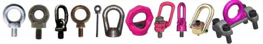
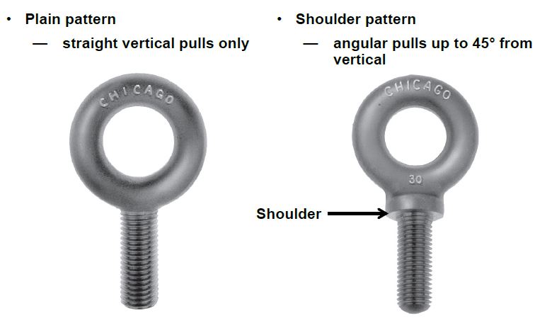
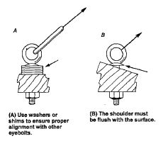
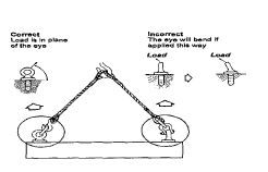
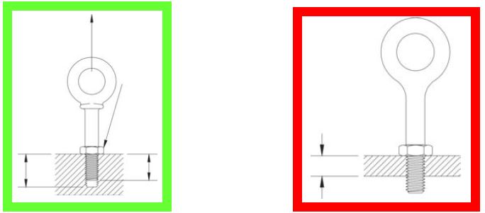
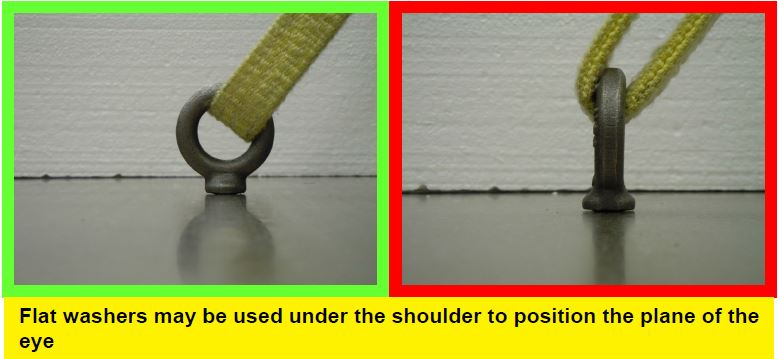
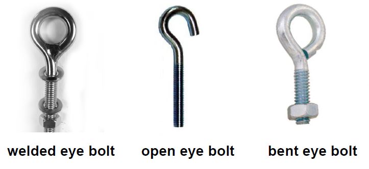
- Seek expert advice when using eyebolts, plate clamps, bull dog grips, chain blocks etc.
- Obtain confirmation that pre-fabricated rebar assemblies such as pad foundations and beams have been fabricated to allow safe lifting.
- Ensure that scaffold towers you are asked to move are designed to be lifted safely.
Don t’s:
- Wrap hand/tag lines around hand or body.
- Use tie wires or banding to lift loads.
- Leave a suspended load unattended.
- Pass loads over the public.
- Use lifting accessories for towing or pulling.
- Ride or climb on machines or suspended loads.
- Lift near power lines.
- Stand or walk beneath a load.
- Connect two or more independently slung loads at different levels on the same lift (sometimes known as chandelier lifts).
 (Figure 1.1) (Figure 1.2)
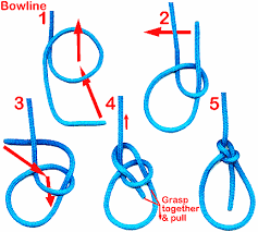

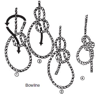
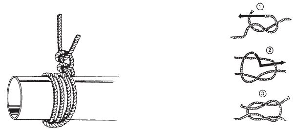
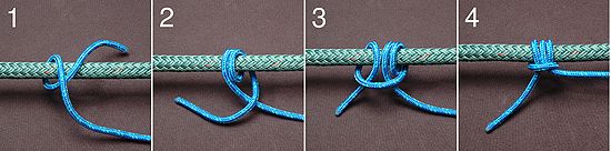
 Running Bowline:
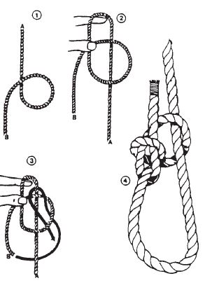


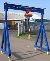
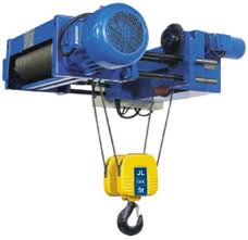
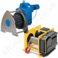
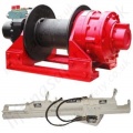
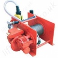
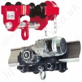
 they as basically a wire rope lifting hoist that are suitable for outdoor use and usually supplied with a bracket and claps for attachment to a scaffolding or to a scaffold tower; the bracket will cantilever out from the scaffolding on a pivot arm that rotates to allow the load once raised to swing above the working platform. There are many different brackets and fixing methods including a counterweight gantry system, this is totally free standing scaffold tower and requires no fixings or fasteners.The lifting capacity for scaffold hoists varies from 100 – 500kg.