Lock Out & Tag Out

OSHA requires employers to establish a Lockout Tag out program and use procedures for affixing appropriate lockout devices or tag out devices to energy isolating devices, and to otherwise disable machines or equipment to prevent unexpected re-energizing, start up or release of stored energy in order to prevent injury to employees.

Energy isolating device:

A mechanical device that physically prevents the transmission or release of energy, including but not limited to the following: A manually operated electrical circuit breaker; a disconnect switch; a manually operated switch by which the conductors of a circuit can be disconnected from all un grounded supply conductors, and, in addition, no pole can be operated independently; a line valve; a block; and any similar device used to block or isolate energy. Push buttons, selector switches and other control circuit type devices are not energy isolating devices.

Lockout: Lockout is one way to control hazardous energy. The placement of a lockout device on an energy isolating device, in accordance with an established procedure, ensuring that the energy isolating device and the equipment being controlled cannot be operated until the lockout device is removed.

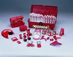
Lockout device: A device that utilizes a positive means such as a lock, either key or combination type, to hold an energy isolating device in the safe position and prevent the energizing of a machine or equipment. Included are blank flanges and bolted slip blinds.

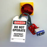
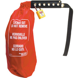
Tag out: Tag out is a labeling process that is always used when lockout is required.The placement of a tag out device on an energy isolating device, in accordance with an established procedure, to indicate that the energy isolating device and the equipment being controlled may not be operated until the tag out device is removed.

Tag out device. A prominent warning device, such as a tag and a means of attachment, which can be securely fastened to an energy isolating device in accordance with an established procedure, to indicate that the energy isolating device and the equipment being controlled may not be operated until the tag out device is removed.

The OSHA standard covers the servicing and maintenance of machines and equipment in which the unexpected start up of machines or equipment, or release of stored energy could cause injury to employees.

Work on cord and plug connected electric equipment for which exposure to the hazards of unexpected start up of the equipment may be controlled by the unplugging of the equipment from the energy source and by the plug being under the exclusive control of the employee performing the servicing or maintenance.

Each Authorized Employee must have and use their own locks & tags –  these must be uniquely identifiable as lockout-tag out material and be identified to the specific worker.

Lockout Tag out Program Elements:

  • Written Program.
  • LOTO Procedure for all equipment.
  • Training for employees.
  • Each Authorized Employee issued separate locks & tags.
  • Locks & Tags are standardized .
  • Use Locks & Tags only for LOTO.
  • Locks & Tags have identification of who placed them.
  • Only the person who placed the lock may remove it .
  • Authorized (Qualified) Employees are the only ones allowed to lock & tagout equipment or machinery

Lock out – tag out Important and purpose:

  • Contact with a hazard while performing tasks that require the removal, by-passing, or deactivation of safe guarding devices.
  • The unintended release of hazardous energy (stored energy)
  • The unintended start-up or motion of machinery, equipment, or processes.
  • Safety devices such as barrier guards or guarding devices are installed on systems to maintain worker safety while these systems are being operated.
  • When non-routine activities such as maintenance, repair, or set-up; or the removal of jams, clogs or misaligned feeds are performed, these safety devices may be removed provided there are alternative methods in place to protect workers from the increased risk of injury of exposure to the unintended or inadvertent release of energy.
  • The main method used and recommended to protect workers from risk of harm in these cases is the use of a lockout/tag out program (LOTO).

de-energization:

De-energization is a process that is used to disconnect and isolate a system from a source of energy in order to prevent the release of that energy.  By de-energizing the system, you are eliminating the chance that the system could inadvertently, accidentally or unintentionally cause harm to a person through movement, or the release of heat, light, or sound.

Types of energy:

Electrical energy is the most common form of energy used in workplaces. It can be available live through power lines or it can also be stored, for example, in batteries or capacitors. Electricity can harm people in one of three ways:

  1. By electrical shock.
  2. By secondary injury.
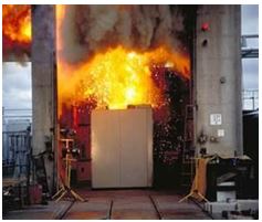
  3. By exposure to an electrical arc.

Hydraulic potential energy is the energy stored within a pressurized liquid. When under pressure, the fluid can be used to move heavy objects, machinery, or equipment. Examples include: automotive car lifts, injection moulding machines, power presses, and the braking system in cars. When hydraulic energy is released in an uncontrolled manner, individuals may be crushed or struck by moving machinery, equipment or other items.

Pneumatic potential energy is the energy stored within pressurized air. Like hydraulic energy, when under pressure, air can be used to move heavy objects and power equipment. Examples include spraying devices, power washers, or machinery. When pneumatic energy is released in an uncontrolled manner, individuals may be crushed or struck by moving machinery, equipment or other items.

Chemical energy is the energy released when a substance undergoes a chemical reaction. The energy is normally released as heat, but could be released in other forms, such as pressure. A common result of a hazardous chemical reaction is fire or explosion.

Radiation energy is energy from electromagnetic sources. This energy covers all radiation from visible light, lasers, microwave, infra red, ultraviolet, and X-rays. Radiation energy can cause health effects ranging from skin and eye damage (lasers and UV light) to cancer (X-rays).

Gravitational potential energy is the energy related to the mass of an object and its distance from the earth (or ground). The heavier an object is, and the further it is from the ground, the greater its gravitational potential energy. For example, a 1 kilogram (kg) weight held 2 metres above the ground will have greater gravitational potential energy then a 1 kg held 1 metre above the ground.

Mechanical energy is the energy contained in an item under tension. For instance, a spring that is compressed or coiled will have stored energy which will be released in the form of movement when the spring expands. The release of mechanical energy may result in an individual being crushed or struck by the object.

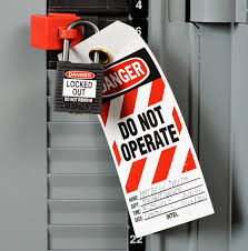
It is important to understand that all of these energy types can be considered as either the primary energy source, or as residual or stored energy (energy that can reside or remain in the system).  Primary energy source is the supply of power that is used to perform work.  Residual or stored energy is energy within the system that is not being used, but when released it can cause work to be done.

For example: when you close a valve on a pneumatic (air) or hydraulic (liquid) powered system, you have isolated the system from its primary energy source. However, there is still residual energy stored in any air or liquid that remains in the system. In this example, removing the residual energy would include bleeding out the liquid, or venting out the air. Until this residual energy is removed from the system, work can occur, whether on purpose or inadvertently.

Not properly assessing and dissipating stored energy is one of the most common causes for workplace incidents that involve hazardous energy. Control of hazardous energy includes isolating the system from its primary power source and residual energy.

Basic steps of locking and tagging out a system:

Lockout and tag out processes involve more than putting a lock on a switch.  They are comprehensive step-by-step processes that involve communication, coordination, and training.

Definitions:

Affected person – is an employee whose job requires them to operate a system, or work in an area in which servicing or maintenance is being performed under lockout/tag out.

Authorized person – is an individual who is qualified to control hazardous energy sources because of their knowledge, training, and experience and has been assigned to engage in such control.

System – refers to machinery, equipment, or processes.

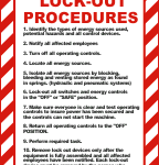
Steps of a lockout/tag out program include:

1. Prepare for shutdown

The authorized person will identify which sources of energy are present and must be controlled and more importantly, identify what method of control will be used. This step involves completing sets of specific work instructions that outline what controls and practices are needed to lock and tag out a system before performing any activity.

2. Notify all affected employees

The authorized person will communicate the following information to notify affected persons:

  • What is going to be locked/tagged out.
  • Why it is going to be locked/tagged out.
  • For approximately how long will the system be unavailable.
  • Who is responsible for the lockout/tag out.
  • Who to contact for more information.

3. Equipment Shutdown

If the system is operating it should be shutdown in its normal manner.  Use manufacturer instructions or in-house work instructions. Equipment shutdown involves ensuring controls are in the off position, and verifying that all moving parts such as flywheels, gears, and spindles have come to a complete stop.

4. Isolation of system from hazardous energy

The exact written instructions will be specific to that system in the workplace. In general, the following are used:

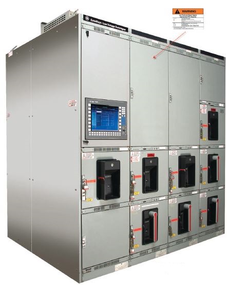
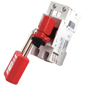
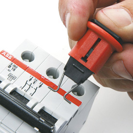
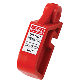
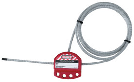
  • Electrical energy – Switch electrical disconnects to the off position.  Visually verify that the breaker connections are in the off position.   Lock the disconnects into the off position.

Electrical lockout
Figure 1: Electrical lockout

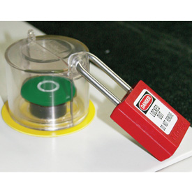
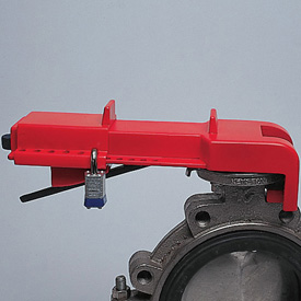
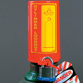
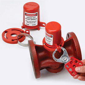
  • Hydraulic and Pneumatic potential energy – Set the valves in the closed position and lock them into place.  Bleed off the energy by opening the pressure relief valves, then closing the airlines.

Hydraulic and Pneumatic lockout
Figure 2: Hydraulic and Pneumatic lockout

  • Mechanical potential energy – carefully release energy from springs that may still be compressed.  If this is not feasible, block the parts that may move if there is a possibility that the spring can transfer energy to it.
  • Gravitational potential energy – Use a safety block or pin to prevent the part of the system that may fall or move.
  • Chemical energy – locate chemical supply lines to the system and close and lockout the valves.  Where possible, bleed lines and/or cap ends to remove chemicals from the system.

5. Dissipation of residual or stored energy

In general, examples include:

  • Electrical energy – To find a specific method to discharge a capacitor for the system in question, contact the manufacturer for guidance. Many systems with electrical components, motors, or switch gears contain capacitors.  Capacitors store electrical energy.  In some cases, capacitors hold a charge in order to release energy very rapidly (e.g., similar to the flash of a camera).  In other cases, capacitors are used to remove spikes and surges in order to protect other electrical components.  Capacitors must be discharged in the lockout process in order to protect workers from electrical shock. 
  • Hydraulic and Pneumatic potential energy – Set the valves in the closed position and locking them into place only isolates the lines from more energy entering the system.  In most cases, there will still be residual energy left in the lines as pressurized fluid.  This residual energy can be removed by bleeding the lines through pressure relief valves.  Contact the manufacturer for more specific details, or if no pressure relief valves are available, what other methods are available.
  • Mechanical potential energy – Carefully release energy from springs that may still be compressed.  If this is not possible, use blocks to hold the parts that may move if the energy is released.
  • Gravitational potential energy – If feasible, lower the part to a height where falling is impossible.  If this is not possible, contact the manufacturer for guidance.
  • Chemical energy – If available, bleed lines and/or cap ends to remove chemicals from the system.

6. Lockout/Tag out

When the system’s energy sources are locked out, there are specific guidelines that must be followed to ensure that the lock cannot be removed, and the system cannot be inadvertently operated.  These guidelines include:

  • Each lock should only have one key (no master keys are allowed).
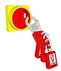
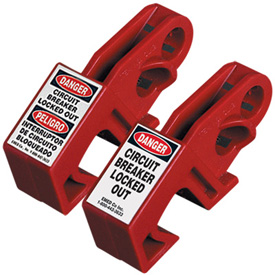
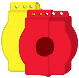
  • There should be as many locks on the system as there are people working on it.  For example, if a maintenance job requires 3 workers, then 3 locks should be present – each of the individuals should place their OWN lock on the system. Locks can only be removed by those who installed them, and should only be removed using a specific process – see step 9 below.

Multiple locks on lockout tag
Figure 3: Example of multiple locks on a lockout tag

7. Verify Isolation

Verify that the system is properly locked out before beginning any work. Verification can take place in several ways:

  • The machine, equipment, or process controls (push buttons, switches, etc.) are engaged or activated and the result is observed. No result means isolation is verified. Return controls to safe position (off).
  • Visual inspection of:
    • Electrical connections to ensure they are open.
    • Suspended parts are lowered to a resting position or blocked to prevent movement.
    • Other devices that restrain machine or process movement.
    • Valve positioning for double block and bleed (for pipes or ducts) – closing two valves of a section of a line, and then bleeding (or venting) the section of the line between the two closed valves.
    • Presence of solid plate used to absolutely close a line – called line blanking (for pipes or ducts).
    • Any other acceptable method of energy isolation.
  • Testing of the equipment:
    • Test circuitry (should be done by a certified electrician) – however, equipment with capacitors needs to be cycled until all energy is drained.
    • Check pressure gauges to ensure hydraulic and pneumatic potential energy has been removed.
    • Check temperature gauges to ensure thermal energy has been discharged.

Choose the method that will best ensure that the energy to the system has been isolated without creating other hazards during the verification.

8. Perform Maintenance or Service Activity

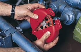
Complete the activity that required the lockout process to be started.

9. Remove Lockout/Tag out devices

To remove locks and tags from a system that is now ready to be put back into service, the following general procedure can be used:

  • Inspect the work area to ensure all tools and items have been removed.
  • Confirm that all employees and persons are safely located away from hazardous areas.
  • Verify that controls are in a neutral position.
  • Remove devices and re-energize machine.
  • Notify affected employees that servicing is completed.

*Note – it is good practice to ensure any individual who placed a lock on the system should also be present when the system is re-started.  This practice helps make sure those employees working on the system are not in a hazardous area when the machine is restarted.

Responsible for the lockout program:

Each party in the workplace has a responsibility in the lockout program. In general:

Management is responsible for:

  • Drafting, periodically reviewing, and updating the written program.
  • Identifying the employees, machines, equipment, and processes included in the program.
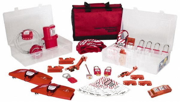
  • Providing the necessary protective equipment, hardware and appliances.
  • Monitoring and measuring conformance with the program.

Supervisors are responsible for:

  • Distributing protective equipment, hardware, and any appliance; and ensuring its proper use by employees.
  • Ensuring that equipment-specific procedures are established for the machines, equipment and processes in their area.
  • Ensuring that only properly trained employees perform service or maintenance that require lockout.
  • Ensuring that employees under their supervision follow the established lockout procedures where required.

Employees are responsible for:

  • Assisting in the development of equipment-specific procedures.
  • Following the procedures that have been developed.
  • Reporting any problems associated with those procedures, the equipment, or the process of locking and tagging out.

DIFFEENT TYPES OF LOCK OUT DEVICES IMAGES FOR GALANCE

UNIVERSAL MDB LOTO

BREAKER LOTO

MCB PIN OUT LOTO

UNIVERASAL FUSE LOTO

PLUG LOTO

PUSH BUTTON LOTO

ADJUSTABLE VALVE LOTO

BUTTERFLY VALVE LOTO

GATE VALVE LOTO

HOIST LOTO

CYLINDER VALVE LOTO

PLUG VALVE LOTO

HASP

CABLE LOTO

LOTO STATION

MCB LOCK OUT DEMO

HASP LOCK OUT DEMO

GATE VALVE LOCK OUT DEMO

 BALL VALVE LOCK OUT DEMO

BUTTERFLY VALVE LOCK OUT DEMO

ADJUSTABLE GATE VALVE LOTO DEMO

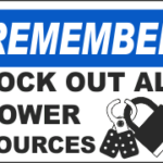
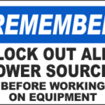
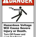
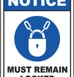
Signage: Lock out and tag out

1 2 3 4 5 6 7 8 9 10 11 12 13 14 15 16 17 18 19 20 21 22 23 24 25 26 27 28 29 30

Dos and Don ts-Lock out and tag out

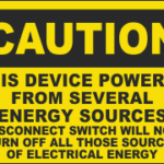
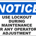
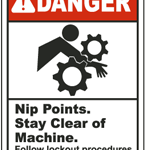
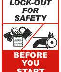
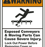
• Follow the Lock Out/Tag Out procedure established by your company.

• Personally de-energize, lock out and tag out all power circuits and electrical equipment before any work is done on such circuits and equipment.

• Personally de-energize, lock out and tag out all start-up switches on mechanical equipment before any work is done on such equipment.

• Make sure that each person working on an electrical circuit or system applies his or her own personal lock and tag.

• Make sure that all persons, including you, are in a safe location before energizing any equipment.

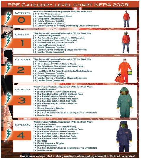
• Wear appropriate Personal Protective Equipment, including electrically rated gloves, hard hat, and eye protection.

• Always maintain de-energizing devices in operable condition.

• Always block machinery against motion even after it has been locked out and tagged out.

• Always familiarize yourself with electrical circuits before you perform any electrical work. Ask for help or consult a wiring diagram/schematic.

• Make sure that electrical work is performed only by a qualified electrician or persons trained to do electrical work under the direct supervision of a qualified electrician.

• Make sure that all electrical circuits and circuit breakers are properly identified before troubleshooting or performing electrical work.

• Check for proper grounding of power conductors where required.

• Use properly rated non-contact voltage testers to ensure that circuits are de-energized.

• Provide an audible or visible warning system to warn persons that a conveyor is starting.

• Maintain electrical meters and testing instruments in good condition to verify that the circuit is de-energized before beginning work.

• Communicate your intentions to work on an electrical circuit to ensure the circuit is, and remains, protected.

• Provide safe access to all working areas.

• Discharge all capacitors after the circuit has been locked out.

• Relieve hydraulic and pneumatic pressure after equipment has been locked out and before performing maintenance.

• Isolate all energy sources, including electric, hydraulic, mechanical and pneumatic, before commencing work.

• Never defeat manual or automatic de-energizing devices.

• Never remove guarding to perform maintenance or inspection until the machine has been properly de-energized and locked out.

• Never perform maintenance or work on moving machines.

• Never rely on someone else to de-energize or disconnect a circuit for you.

• Never remove someone else’s lock or tag.

• Never perform work on an electrical circuit before testing to make sure it has been de-energized.

• Never remove or disturb an electrical lock or tag.

• Never assume that a circuit breaker will not be reset by someone else. Always lock it out.

• Never loan or share your lock or key with someone else.

Click the below link to download lock out and tag out documents

Tool Box Talk – Loto

 inspection-form-lockout-tagout

 lockout-tagout

 lockout-tagout-program-audit

 management-lockout-tagout-survey
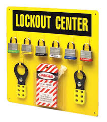
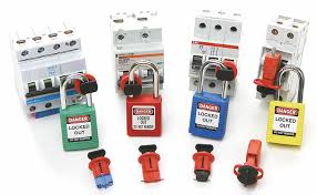
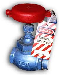
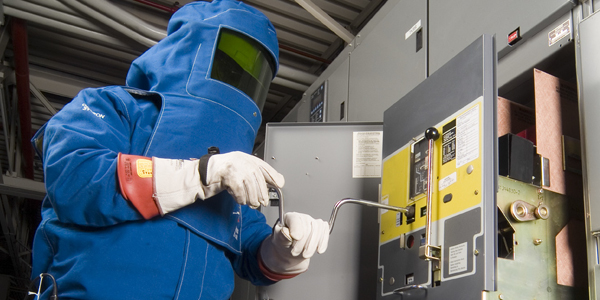
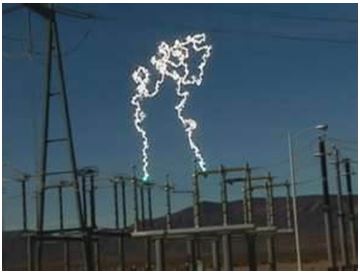
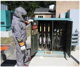
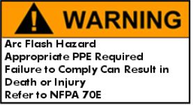
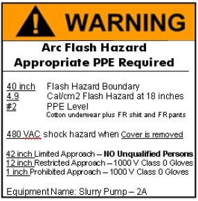
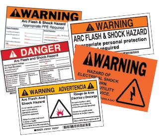
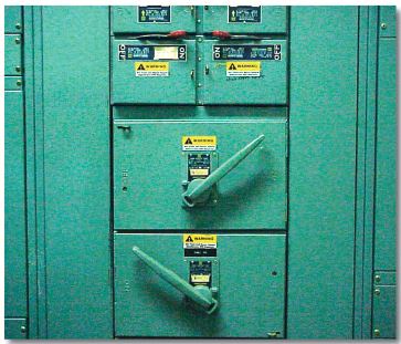
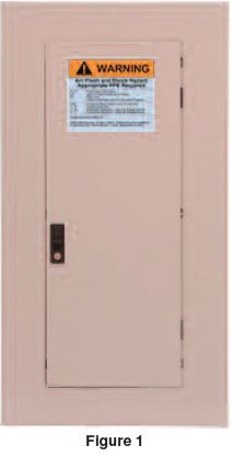
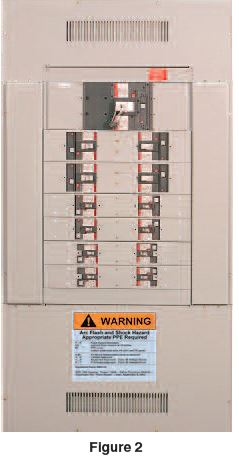
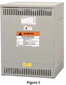
 

Arc Flash Safety

Arc Flash Safety

What is an Arc Flash?

An arc flash is a short circuit through air that flashes over from one exposed live conductor to another conductor or to ground.

Simply put, an arc flash is a phenomenon where a flash over of electric current leaves its intended path and travels through the air from one conductor to another, or to ground. The results are often violent and when a human is in close proximity to the arc flash, serious injury and even death can occur.

Arc flash can be caused by many things including:Arc Flash Icon

  • Dust
  • Dropping tools
  • Accidental touching
  • Condensation
  • Material failure
  • Corrosion
  • Faulty Installation
  • Coming close to a high-amp source with a conductive object can cause the electricity to flash over.
  • Dropping a tool or otherwise creating a spark can ignite an arc flash
  • Equipment failure due to use of substandard parts, improper installation, or even normal wear and tear
  • Breaks or gaps in insulation.

Three factors determine the severity of an arc flash injury:

  • Proximity of the worker to the hazardWelder
  • Temperature
  • Time for circuit to break

Because of the violent nature of an arc flash exposure when an employee is injured, the injury is serious – even resulting in death. It’s not uncommon for an injured employee to never regain their past quality of life. Extended medical care is often required, sometimes costing in excess of $1,000,000.

Definitions

Arc Flash Boundary (ARC) – is the distance at which an electrical arc can flash outward, which may endanger employees working on electrical equipment.

Flash Protection Boundary (FPB) – the calculated safe working distance from electrical equipment which would not expose the employee to the hazards associated with an electrical arc flash.

Electrical Assessment – an analytical evaluation which would calculate the arc flash potential of an electrical component 1 hazard, used to establish the flash protection boundary and the correct level of required PPE, determined by an electrical engineer or the equivalent.

Qualified Employees (per NFPA 70E, 2000 Edition, Standard for Electrical Safety Requirements for Employee Workplaces) – a qualified person shall be trained and knowledgeable of the construction and operation of equipment or a specific work method, and be trained to recognize and avoid the electrical hazards that might be present with respect to that equipment or work method.

Such persons shall also be familiar with the proper use of special precautionary techniques,personal protective equipment, insulating and shielding material!, and insulating tools and test equipment. A person can be considered qualified with respect to certain equipment and methods but still be unqualified for others. Such persons permitted to work within limited approach of exposed energized conductors and circuit parts shall at a minimum, be additionally trained in the following;

  • The skills and techniques necessary to distinguish exposed energized parts from other parts of the electric equipment.
  • The skills and techniques necessary to determine the nominal voltage of exposed energized parts.
  • The approach distance specified in the tables and the corresponding voltage to which the qualified person will be exposed.
  • Employees will be capable of reading and understanding the attached PPE matrix, and listed approach boundaries and hazard risk category tables, which are necessary to perform the task safely.

Typical Results from an Arc Flash:arcflash.jpg

  • Burns (Non FR clothing can burn onto skin)
  • Fire (could spread rapidly through building)
  • Flying objects (often molten metal)
  • Blast pressure (upwards of 2,000 lbs. / sq.ft)
  • Sound Blast (noise can reach 140 dB – loud as a gun)
  • Heat (upwards of 35,000 degrees F)

Current Arc Flash Boundaries:

The arcflash boundaries are designed to keep employees safe while they are working near energized equipment.

  • “Prohibited Approach Boundary” removed
  • Conductive articles of jewelry and clothing must be removed
  • Working space shall not be used for storage
  • Barricades shall not be placed closer than the arc flash boundary when it is greater than the limited approach boundary
  • Insulated tools must be used when working inside the restricted approach boundary

NFPA 70E 2015 Changes

The NFPA 70E gets updated every three years. The 2015 update includes some of the following changes:

Blue ArrowRevision to arc flash warning label content

Blue ArrowElimination of PPE Hazard Category “0”

Blue ArrowElimination of the Prohibited Approach Boundary

Blue ArrowAdditional boundary requirements

Blue ArrowRevisions to selecting appropriate personal protective equipment (PPE)

Blue ArrowUpdated training and retraining requirements

Blue ArrowMinor terminology changes (such as “work shoes” becomes “footwear”)

Flash Protection Boundary (outer boundary):

The flash boundary is the farthest established boundary from the energy source. If an arc flash occurred, this boundary is where an employee would be exposed to a curable second degree burn (1.2 calories/cm2). The issue here is the heat generated from a flash that results in burns.

Limited Approach:

An approach limit at a distance from an exposed live part where a shock hazard exists.

Restricted Approach:

An approach limit at a distance from an exposed live part which there is an increased risk of shock.

Prohibited Approach (inner boundary):

A distance from an exposed part which is considered the same as making contact with the live part.

This distance is not common between equipment. Some equipment will have a greater flash protection boundary while other equipment will have a lesser boundary.

Ways to Protect the Workers

There exists a number of ways to protect workers from the threat of electrical hazards. Some of the methods are for the protection of qualified employees doing work on electrical circuit and other methods are geared towards non-qualified employees who work nearby energized equipment.

Here are a few of the protective methods:

  • De-energize the circuit
  • Work Practices
  • Insulation
  • Guarding
  • Barricades
  • Ground Fault Circuit Interrupters (GFCI)
  • Grounding (secondary protection)

If You Must Work on Energized Circuits

If it has been determined that de-energizing a circuit is not feasible and the employee must work “hot”, the employer shall develop and enforce safety-related work practices to prevent electric shock or other injuries resulting from either direct or indirect electrical contacts.

The specific safety-related work practices shall be consistent with the nature and extent of the
associated electrical hazards.

These safety related work practices could include:

  • Energized Electrical Work Permit
  • Personal Protective Equipment
  • Insulated Tools
  • Written Safety Program
  • Job Briefing

Additional Boundary Requirements:

Conductive Articles of Jewelry and Clothing – Watchbands, bracelets, rings, key chains, necklaces, metal frame glasses, etc. shall not be worn within the restricted approach boundary.

Working Space – Shall not be used for storage. Space shall be kept clear to permit safe operation and maintenance.

Barricades – When the arc flash boundary is greater than the limited approach boundary, barricades shall not be placed closer than the arc flash boundary.

Insulated Tools – Employees shall use insulated tools when working inside the restricted approach boundary of exposed energized electrical conductors.

Understanding the Arc Flash Warning Labels

Each piece of equipment operating at 50 volts or more and not put into a de-energized state must be evaluated for arc flash and shock protection. This evaluation will determine the actual boundaries (i.e. prohibited, limited, restricted etc) and will inform the employee of what PPE must be worn.Arc Flash Printer

Once the evaluation is complete an Arc Flash Hazard warning label must be affixed to the equipment and readily accessible to employees who may work on the energized equipment.

To increase safety and ensure compliance throughout the workplace, it is essential to identify arc flash hazards in your facilities. Arc flash labeling is an important responsibility that should be addressed by the employer and includes the labeling of electrical equipment, such as switchboards, panel boards, industrial control boards, meter socket enclosures and meter control centers.

These labels should have relevant information to keep employees safe, including nominal system voltage, arc flash boundary and personal protective equipment information.


Minimum arc flash label example         Detailed (preferred) arc flash label example

What Needs to be Labeled?

Arc flash labeling is the responsibility of the employer, not the manufacturer or installer of the equipment. The NEC provides the following examples of electrical equipment that must be field marked with a warning label (This is not an all inclusive list):

  • Switchboards
  • Panel boards
  • Motor control centers
  • Industrial control panels
  • Meter socket enclosures

Labeling is required for any piece of electrical equipment that is likely to require examination, adjustment, service or maintenance while energized, creating the potential for an arc flash incident to occur. Thus, many employers are also labeling bus ducts and other electrical equipment not specifically called out in the NEC (National Electrical Code).

Any modifications or renovations to electrical equipment that will change data on the label will require an updated arc flash risk assessment and label according to the 2015 NFPA 70E standard. At minimum, the safety program needs to be audited at intervals not to exceed 3 years and arc flash risk assessment shall be periodically reviewed at intervals not to exceed 5 years.

The labeling requirements for equipment installed prior to the 2002 NEC Provision are not specifically stated.
However, OSHA’s general duty clause for hazard warning may apply here. Should the equipment be modified or upgraded in any way, then a label must be affixed. In fact, an OSHA representative has stated that even changing a fuse or circuit breaker could be considered a modification that would require labeling. Labels applied prior to September 30, 2011 are acceptable if they contain the available incident energy or required level of PPE.

From a safety perspective, the hazard is the same regardless of when the equipment was installed. Consequently, most employers are simply labeling all the appropriate equipment, regardless of when it was installed.

The NEC requirement states that the marking must be in a location that is clearly visible to qualified persons before they begin work. Typically, the label is placed outside the panel or enclosure door. In some cases,companies choose to put the label inside the door to protect it from harsh environments; however, this should only be done if the door must be opened (allowing the label to be seen) in order to remove the panel face or enclosure. The key point is that the label should be easily noticeable by workers before they may be exposed to any potentially dangerous live parts.

What Needs to Appear on the Label?

Neither the NFPA 70E nor the NEC requirements specify whether to use a “Danger” or “Warning” header; however, NFPA 70E does recommend identifying those situations in which there is a hazard to the worker. A commonly used guideline is to use a red “Danger” header when the voltage is over 600 volts or when the incident energy is over 40 cals/cm2. Many employers have also

standardized to using the “Danger” signal word to indicate a situation where serious injury or death WILL occur. If it is less than that threshold, an orange “Warning” header is used. The employer has the final decision on which words appear on the labels, but it is imperative that consistency be maintained on all the labels throughout the facility.

It is also important to note that arc flash labels must be able to withstand their usage environment. This means that the print should not fade and the adhesive should be aggressive enough to avoid peeling. When necessary, an over laminate should be applied to protect the printed surface from harsh chemicals and exposure to sunlight.

How Many Labels per equipment?

A frequently asked question is how many labels are enough? Obviously if one is good, more is better – right? This philosophy has both positive and negative aspects that must be considered. The more labels used the higher the visibility factor. However, too many labels clutter the objective and cause workers to ignore the warning.

For the MCC above, a simple one-word “warning” label was used without providing specific PPE, boundary information, or hazard levels. This minimizes clutter, however, if you take a step back and see 50-75 of these labels the clutter becomes obvious. The clutter is even more prevalent and confusing if the standard AFH information is included on the labels. The worker looking at the MCC must then determine


1) Which label is important?

2) If the labels are different, what information applies to this task?

3) How do I react to these circumstances?

Examples

This section provides multiple labeling examples for different types of electrical equipment, which can be modified or extrapolated to fit your system. For some equipment types, multiple options will be provided.

Panels

Panels are typically of box construction with a fixed backing plate attached to a beam/ wall mounted. The front of the panel, which provides opening access, is bolted in place. The front cover typically has a hinged opening, which allows viewing and operation of the breakers. For standard 42 circuit
lighting panels, the typical labeling procedure is one label on the main cover, top center. See Figure-1.

Panel boards

Panel boards, sometimes called distribution panel boards (DPB), or distribution boards are larger than a standard panel and may range from 400-1200A. They are typically standalone, but smaller units may be wall or beam mounted. Larger units may be accessible front and back side via bolted covers. For standard DPB’s, typical labeling procedures is one label on the main cover, top center. For the example shown in Figure-2, the label was moved to the bottom to prevent covering the cooling vents. Panel boards, do not have isolated and barrier protected main breakers unless specially ordered and should always have only one label.

Dry Type Transformers

Dry type transformers typically have a bolted on face plate section with exposed terminals behind the face plate. Since this is the main access point, it is usually not necessary to label the other sides.Figure-3

Variable Frequency Drives,and Control Cabinets

Variable frequency drives and control cabinets are typically hinged front opening units with an open, exposed incoming main breaker. The incoming breaker or fuse is typically not isolated or barrier protected from the other sections and therefore cannot be used for AFH protection. Like other cabinets, one “worst case” label is typically sufficient. See Figure-4.

Switchboards and Switch gear

Switchboards and Switch gear are the standard for low voltage distribution equipment. Switch gear by definition has isolated and barrier protected cubicles, rack-in air frame breakers/switches, and isolated bus. Switchboards may have similar attributes but will most likely be equipped with molded case or insulated case breakers, or fuses in non-isolated cubicles with non-isolated bus work. By special order, the main breaker/switch can be isolated, enhancing arc flash protection.For a typical 4 section or less switch gear lineup, only one label (worst case) on the front side is necessary. For longer sections additional labels can be applied every 5-10 feet. Since both front and back-side switch gear covers are hinged, the back-side covers should also be labeled.

For switchboards, the back-sides are typically open exposed bus with bolted covers, which should prevent access. Labeling should be optional since access is not easily obtained.

Do’s and Don’ts of AFH labeling:

Do’s

  • Do label “WORST” case energy or PPE level. Consider all possible modes of operation.
  • Do label per ANSI Z535.4
  • Do label using only one color, Orange for Warning or Red for Danger.
  • Do standardize on only one working distance – preferably 18 inches for all labels in a facility.
  • Manage down PPE levels using work permits stating increased distances based on work task and proper safety procedures.
  • Label to warn of potential danger, not for the purpose of working on the equipment.
  • Do use common sense in your hazard labeling.
  • Do implement NFPA 70E Article 130.1 work permit requirements for all energized work even if a label is present.

Don’ts

  • Do not label each MCC bucket, breaker/fuse cubicle, or plug-in (busway).
  • Do not label using colors for PPE level.
  • Don’t label with multiple distances or PPE levels on the same equipment.
  • Don’t make it complicated.
  • Don’t substitute labeling for NFPA 70E Article 130.1 work permit requirements.

Personal and Other Protective Equipment:

A. General

Employees working in areas where electrical hazards are present shall be provided with, and shall use, protective equipment that is designed and constructed for the specific part of the body to be protected and for the work to be performed.

B. Care of Equipment

Protective equipment shall be maintained is a safe, reliable condition. The protective equipment shall be visually inspected before each use.

C. Personal Protective Equipment

1. General

When an employee is working within the Flash Protection Boundary he/she shall wear protective clothing and other personal protective equipment in accordance with NFPA 70E.

2. Movement and Visibility

When flame-resistant (FR) clothing is worn to protect an employee,it shall cover all ignitable clothing and shall allow for movement and visibility.

3. Head, Face, Neck, and Chin Protection

Employees shall wear non-conductive head protection wherever there is a danger of head injury from electric shock or burns due to contact with live parts or from flying objects resulting from electrical explosion. Employees shall wear non-conductive protective equipment for the face, neck, and chin whenever there is a danger of injury from exposure to electric arcs of flashes or from flying objects resulting from electrical explosion.

4. Eye Protection

Employees shall wear protective equipment for the eyes whenever there is danger of injury from electric arcs, flashes, or from flying objects resulting from electrical explosion.

5. Body Protection

Employees shall wear FR clothing wherever there is possible exposure to an electric arc flash above the threshold incident-energy level for a second-degree burn. 5 J/cm2 (1.2 cal/cm2). Such clothing can be provided as shirt and trousers, or as coveralls, or as a combination of jacket and trousers, or, for increased protection, as coveralls with jacket and trousers. Various weight fabrics are available. Generally, the higher degree of protection is provided by heavier weight fabrics and/or by layering combinations of one or more layers of FR clothing. In some cases one or more layers of FR clothing are worn over flammable, non melting clothing. Non-melting, flammable, clothing, used alone, can provide protection at low incident energy levels of 8.36 J/cm2 (2.0 cal/cm2) and below.

6. Hand and Arm Protection

Employees shall wear rubber insulating gloves where there is danger of hand and arm injury from electric shock due to contact with live parts. Hand and arm protection shall be worn where there is possible exposure to arc flash burn.

7. Foot and Leg Protector

Where insulated footwear is used as protection against step and touch potential,dielectric overshoes shall be required. Insulated soles shall not be used as primary electrical protection.

8. Selection of Personal Protective Equipment

When Required for Various Tasks When selected in lieu of the flash hazard analysis, NFPD table 130.7(C)(9)(a) shall be used to determine the hazard risk category for a task. The assumed short-circuit current capacities and fault clearing times for various tasks. Systems with greater than the assumed fault clearing times, a flash hazard analysis shall be required.

Both larger and smaller available short-circuit currents could result in higher available arc-flash energies. If the available short circuit current increases without a decrease in the opening time of the over current protective device, the arc-flash energy will increase. If the available short-circuit current decreases, resulting in a longer opening time for the over current protective device, arc flash energies could also increase.

Factors in Selection of Protective Clothing

Clothing and equipment that provide worker protection from shock and arc flash hazards shall be utilized. Clothing and equipment required for the degree of exposure shall be permitted to be worn alone or integrated with flammable , non melting apparel. If FR clothing is required, it shall cover associated parts of the body as well a all flammable apparel while allowing movement and visibility.

All personal protective equipment shall be maintained is a sanitary and functionally effective condition. Personal protective equipment items will normally be used in conjunction with one another as a system to provide the appropriate level of protection.

Layering

Non melting, flammable fiber garments shall be permitted to be used as under layers in conjunction with FR garments in a layered system for added protection. If non melting, flammable fiber garments ate used as under layers the system arc rating shall be sufficient to prevent break open of the innermost FR layer at the expected arc exposure incident energy level to prevent ignition of flammable under layers. A typical layering system might include cotton shirt and trouser, and a FR coverall. Specific tasks might call for additional FR layers to achieve the required protection level.

Outer Layers

Garments worn as outer layers over FR clothing, such as jackets or rain wear, shall also be made from FR material.

Under layers

Melt able fibers such as acetate, nylon, polyester, polypropylene, and spandex shall not be permitted. in fabric under layers (underwear) next to the skin.

Coverage

Clothing shall cover potentially exposed areas as completely as possible. Shirt sleeves shall be fastened at the wrist, and shirts and jackets shall be closed at the neck.

Fit

Tight-fitting clothing shall be avoided. Loose fitting clothing provides additional thermal insulation because of sir spaces. FR apparel shall fit properly such that it does not interfere with the work task.

Interference

The garment selected shall result in the least interference with the task but still provide the necessary protection. The work method,location, and task could influence the protective equipment selected.

Click the below link to download the guidelines,PPT and safety check sheet

arc-flash-checklist

arc-flash-safety-ppt-1

arc-flash-safety-ppt-2

arc_flash_labeling_whitepaper


Arc Flash Safety Training Video

Arc Flash PPE Laboratory Test Video

Electrical Do & Donts

Dos and Dont’s – Fire safety-Electricity

1. Use I.S.I. certified appliances.

2. Use good quality fuses of correct rating, miniature circuit breakers and earth leakage circuit breakers.

3. Use one socket for one appliance.

4. Switch off the electric supply of the fire affected areas.

5. Fuses and switches should be mounted on metallic cubicles for greater safety against fire.

6. Replace broken plugs and switches.

7. Keep the electrical wires away from hot and wet surface.

8. Switch off appliance after use and remove the plug from the socket.

9. Switch off he ‘Main’ switch when leaving home for a long duration.

1. Don’t use substandard fixtures, appliances.

2. Never have temporary or naked joints on wiring.

3. Don’t lay wires under carpets, mats or doorways. They get crushed, resulting in short circuiting.

4. Don’t lay wires under carpets, mats or doorways. They get crushed, resulting in short circuiting.

5. Don’t allow appliances cords to dangle.

6. Don’t place bare wire ends in a socket.