Safety Net

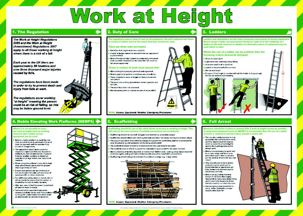
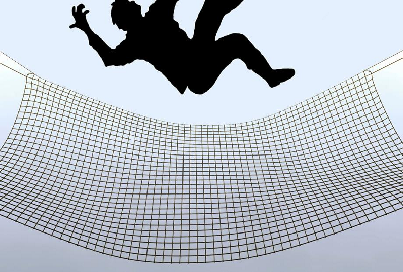
Regardless of the time spent on a roof, the risk of falling is high. Any fall is likely to result in a serious injury. Safety nets installed below a high-level work area reduce the distance that a worker can fall.

They absorb the impact of the fall and provide a ‘soft landing’ to reduce the likelihood of a person being injured.

Safety nets are collective fall arrest systems, not fall restraint systems. That is, they provide passive protection from falls while allowing people to work at height without restricting their movement.

Collective fall arrest systems include:

  • Safety nets
  • Soft landing systems, or fall arrest mats.

PURPOSE:

This Best Practice Guideline covers the safety requirements and safe use of safety nets to protect people from being injured by a fall from a height. This information is for anyone who has to provide a safe place of work and make sure that all plant and equipment is safe.

It describes best practice for:

  • safety net design principles
  • types and classifications of safety nets
  • safety net components
  • installing of safety nets
  • Inspection, repair and maintenance of safety nets.

REFERENCED STANDARDS:

This guide follows the test methods, installation procedures & safety net positioning limits described in the following British and European codes of practice and standards:

  • BS 8411 (Code of practice for safety nets on construction sites and other works)
  • BS EN 1263-1 (Safety nets – Part 1: Safety requirements, test methods)
  • BS EN 1263-2 (Safety nets – Part 2: Safety requirements for the positioning limits).

DEFINITIONS

Anchorage device (safety nets)

A device or system used to connect a safety net to the structure. May include tie ropes, karabiners or other attachment devices.

Anchor point

A fixing on the structure that the safety net is attached to.

Border rope:

A rope that passes through each mesh around the net’s perimeter and determines the net’s overall dimensions.

Class

The safety net classification based on the mesh size and energy absorption capacity.

Clearance distance

The distance below the net that must be kept clear of objects that a falling person might otherwise strike as the safety net deflects under their impact.

Coupling rope

The rope that joins two safety nets together.

Fall height

The vertical distance between a work platform and the safety net.

Initial sag

The amount of sag due to the net’s self-weight.

Mesh

A series of ropes arranged in either a square or diamond pattern to form a net.

Mesh rope

The rope used to make the net’s meshes.

Mesh size

The distance from centre to centre of the mesh.

Net system

The safety net, tie ropes or other anchorage devices, and the supporting structure linked together to provide a collective fall arrest system.

Safety net

The combination of mesh, border ropes, test meshes and labels of the net.

Supporting structure

The structure to which the safety net is attached.

PRINCIPLES OF SAFETY NET DESIGN

Safety nets are designed to progressively deflect (stretch) and absorb the energy of a fall, so a falling person is less likely to be injured. The greater the fall height, the greater the impact; so the net’s deflection must also be greater. The safety net must be able to deform or deflect enough to absorb all of the energy from the fall’s impact up to the maximum fall height for the design.

There must be enough clear distance below the net so that the person falling does not hit an obstacle or the ground while the net is deflecting.

SAFETY NET SYSTEMS

This guideline is for ‘System S’ safety nets, which are horizontally-installed safety nets with a continuous border rope. Safety nets may be either knotted or knotless with a square (Q) or diamond (D) mesh arrangement.

Notes:

  • When a load lands on a knotted net, the knots near the impact tighten.The tightening is permanent and reduces the amount of energy the net can absorb from further impacts. Knotless nets do not have this problem.
  • A person who falls onto a knotless net is less likely to receive facial injuries.
  • Square mesh is more popular than diamond mesh, with no obvious reason for the preference, according to research in the UK.
  • Square mesh has less sag when rigged so at its mid-point, it is closer to the work level.

SAFETY NET CLASSIFICATION

BS EN 1263-1 lists four classes of nets:

  • Classes A and B describe the net’s maximum energy absorption capacity (that is, how much energy it can absorb), measured in kilojoules (kJ). For example: class A = 2.3 kJ; class B = 4.4 kJ
  • classes 1 and 2 describe the mesh sizes. For example: class 1 = 60 mm; class 2 = 100 mm.

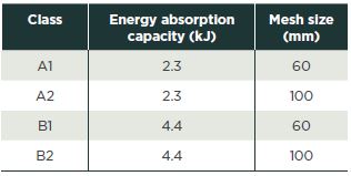
Table 1 sets out the net classifications.

Both classes A1 and A2 nets are suitable for system S safety nets. Class A2 nets (2.3 kJ energy absorption capacity and 100 mm mesh size) are most commonly used as the larger mesh size is lighter and has less initial sag.

Mesh rope:

Mesh rope should be made from at least three separate strands, braided so they cannot unravel. It should be tested according to BS EN 1263-1, clause 7.3.

Border rope:

A border rope is a continuous rope passing through each mesh around the perimeter of S safety nets. It should have a minimum tensile strength of 30kN, and be tested according to BS EN 1263-1, clause 7.5.

Tie rope:

Tie ropes fasten the safety net to the structural elements and/or the anchor points on the structure being netted. They should have a minimum tensile strength of 30kN and be tested according to BS EN 1263-1, clause 7.5.

Coupling rope:

Coupling ropes join safety nets together when more than one net is needed to protect an area. They should have a minimum tensile strength of 7.5kN and tested according to BS EN 1263-1, clause 7.5.

SAFETY NET LABEL

All safety nets should have a label showing the:

  • manufacturer’s name and article code
  • date of manufacture
  • class and size of net
  • mesh size and configuration
  • net’s unique identity or serial number (ID)
  • net’s minimum energy absorption capacity
  • type of ongoing net inspections.

The label must be permanently attached to the net and be legible throughout the net’s life.

SIZE OF SAFETY NETS

BS EN 1263-2 only applies to safety nets over 35 m2 and where the shortest side is at least 5.0 metres.

If the fall height is over 2.0 metres, the safety net must:

  • be larger than 35m2
  • have the shortest side at least 5.0 metres, and
  • have a maximum fixing spacing of 2.5 metres.

SAFETY NETS LESS THAN 35 M2

If a load falls onto a net less than 35 m2, the small net area means there will be less deflection and more limited energy absorption compared to nets with a larger area. System S safety nets that are less than 35 m2 are not covered by BS EN 1263-2.
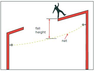
FALL HEIGHT

The fall height is the distance a person will fall from the work platform onto the safety net – see Figure 2. A greater fall height results in a greater fall impact.

Keep the fall height as low as possible by installing safety nets as close as practicably possible below the work platform. Where possible, install nets no more than 2.0 metres  below the work platform. Note that BS EN 1263-2 allows a maximum fall height of 6.0 metres (this gives a nominal fall height of 7.0 metres from a person’s centre of gravity) but this applies only to nets that are more than 35 m2 (see section 2.10 Size of safety nets).

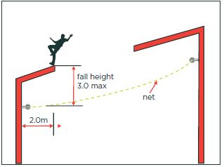
Within 2.0 metres of the net’s outer edges, the fall height between the work platform and net should be no more than 3.0 metres. This is because safety nets cannot deflect as much at corners and edges (BS EN 1263-2).

Figure 2: Fall heights.  Figure 3: Fall height with 2.0 m of outer edge of net.

 CLEARANCE DISTANCES

There must be enough clearance below the safety net to allow for it to deform when a person falls onto it. The amount it will deform depends on the height of the fall and the span of the net. See Figure 4.

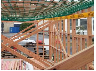
The graph in Figure 5 (from BS EN 1263-2: Figure 4) shows typical deformation when an object lands on the net. It is based on fall height and can be used to calculate the minimum clearance distance needed below the net, but only applies where the:

  • area of the net is more than 35 m2
  • shortest side of the net is at least 5.0 m
  • initial sag is no more than 10% of the smallest side of the net, and
  • fall height is no more than 6.0m .                                                                                                              Figure 4

Figure-4 Temporary bracing means that there is not enough clearance below the nets. A person fallingonto the net is likely to strike the timber bracing.This is not best practice.

As an additional safety factor BS 8411: 2007recommends allowing an extra 0.5 metreclearance below the net.

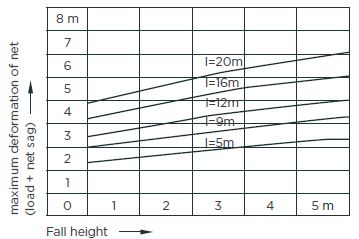
Figure 5: Deformation of net when an object falls on it.

NET SAG:

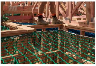
Net sag, or initial sag, is the amount of deformation from the net’s own weight. Net sag should be between 5% and 10% of the net’s shortest side.To have enough initial sag, the safety net should be at least 10% larger (along both sides) than the area it is going to cover. Excess netting should be under-rolled into the tie rope or attachment system (see Under-rolling) to spread the load evenly and avoid too much stress on individual meshes.

        Figure-6 Safety net with between5-10% initial sag.

OVER-TENSIONING AND UNDER-TENSIONING

Safety nets should not be over-tensioned as they must be able to deflect and absorb energy from the impact of a fall. An overtensioned net, or a net with too many fixing points, may not be able to deflect enough. In either case, the impact on the person falling onto the net increases, as well as increasing the load imposed on the net and structure. An under-tensioned net may deflect too much and if there isn’t enough clearance below the net, a falling person may hit an obstacle or the ground.

CATCHING WIDTH

If a person trips when they are moving forward, they fall forward as well as downward. The distance they fall forward is affected by the height of the fall; that is, the higher the fall, the further the forward movement. Nets providing protection at the edge of a work platform must be wide enough to include the falling person’s forward movement – see Figure 7. The width of the net between the edge of the work platform and the outer edge of the safety net is called the catching width.

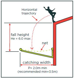
Figure 7: Catching width

BS EN 1263-2: Table 2 sets out minimum catching widths for maximum fall heights – see Table 2 of this guide. As an added safety factor, BS 8411 recommends extending the net at least 1.5 metres beyond the distances given in Table 2 of BS EN 1263-2.

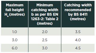
Table 2: Catching widths for maximum fall heights
(from BS EN 1263:2, Table 2 and Clause 4.3).

Cathching width where the slope of the working platform is more 20 deg:

If the slope of the working platform is more than 20°:

  • the catching width must be at least 3.0 metres, and
  • the distance (t) between the work platform’s edge and the lowest point of the safety net’s outside edge should be no more than 3.0 metres. See Figure 9.

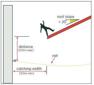
Figure 8: Fall heights where working platform has a slope of more than 20 deg.

PLANNING:

Plan the installation before installing a safety net. You should consider:

  • the installation (rigging) and dismantling (striking) sequence
  • providing and locating anchor points
  • how to keep the right clearance distance below the safety net
  • the means of access for rigging and striking
  • he means of access for inspection, temporary repairs and removing debris, and
  • a rescue plan.

Planning should include everyone involved in supplying, installing and using nets, including:

  • the permanent works designer
  • net supplier/installer
  • main contractor/site supervisor
  • roofing contractor.

Designer’s Role:

The designer’s role includes:

  • designing suitable anchorage points
  • avoiding details that make safety net installation difficult or dangerous.

INSTALLER’S ROLE

The installer rigs (installs) and strikes (dismantles) the nets. Before starting installation, the installer should give the main contractor or site supervisor information about:

  • their training and qualifications2 for installing safety nets
  • the testing, maintenance and energy absorption capacity of the nets
  • the plant they intend to use to install the nets
  • the access facilities they need
  • the anchor points and/or fixing requirements
  • clearance distance requirements
  • a rescue plan
  • how to protect workers below the net.

They should also:

  • check anchor points
  • make sure anchor points are suitable for the loads
  • make sure the nets are fit for purpose
  • make sure there is enough clearance under the nets.

Once the nets have been installed, the installer should give handover documentation to the main contractor/site supervisor. The documents should verify the safety net system is fit for purpose, as well as giving written instructions on:

  • rescue procedures
  • inspection procedures
  • removing debris from the nets.

The installer should also give verbal instructions on all procedures. Everyone who may be involved in a rescue must have rescue training.

SAFETY NET INSTALLATION HIERARCHY

A hierarchy of safety net installation minimises risk to the riggers. The hierarchy goes from low to high risk as follows:

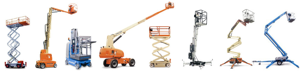
1. At ground level with a remote anchorage attachment
2. Using a mobile elevating work platform (MEWP). See Figure 9.
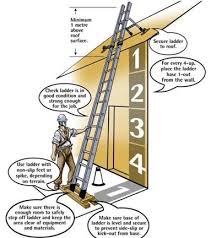
3. Using a ladder for short-duration work, but only after carrying out a hazard assessment
4. Using rope access techniques.                                                               Figure 9

Notes:

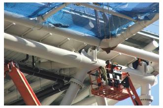
1. Mobile access towers (or mobile scaffoldtowers) are not recommended for installing safety nets as they can catch in the nets when moving around.

2. Rope access work is highly specialised. Only trained and competent people should do rope access work.

Figure 9: Safety net installation using a mobile elevating work platform.

Inspecting net before installation:

Before installing the nets, the installer should:

  • examine the safety nets on both sides for damage or defects
  • check the net’s labels (manufacturer’s and removable test mesh) are displayed, current and valid.

If the installer finds any damage or defects, the net should not be used. If the damage is reparable, the net may be repaired; otherwise it must be withdrawn from service. If a label is not attached, or the label’s information is not legible, do not use the net.

Installation (Generally)

  • Install safety nets as close as possible to the work platform.
  • Rig safety nets to follow the roof line.
  • Nets should not restrict the construction work.

Ceiling battens must not be installed until the safety nets have been removed. If they are installed before or with safety nets in place, the battens will be the first obstacle the falling person hits. Before installing nets near live wires or overhead power cables, contact the line owner to make the wires or cabling safe.

Net Access:

Nets must be easily accessible to carry out a rescue or clear debris. Provide access by:

  • installing the nets next to a work platform
  • installing the nets next to the work platform’s access point
  • providing an access platform next to the net.

People should be able to remove debris fromthe nets without walking on them. Do not usesafety nets to collect debris, for storage, as a work platform, or for providing access to a work platform.

Anchor Points:

Safety nets are attached with tie ropes or karabiners to the supporting structure or to specifically-designed anchor points on the structure.Based on a maximum fall height of 6 metres and an assumed load angle of 45°to the horizontal, each anchor point should have a 6 kN minimum load carrying capacity– see Figure 10. The combined load-carrying capacity of the supporting structure applied over three adjacent anchor points should be at least 4 kN, 6 kN, 4 kN.

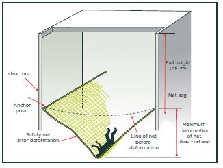
Figure 10: Minimum load-carrying capacity of anchor points.

The maximum distance between anchor points according to BS EN1263-2 is 2.5metres recommends installing anchor points at between 1.5 and 2.0 metre centres.

Safety nets used in residential, timber frame construction may need to be attached at closer centres.
Anchor points and the supporting structure that the safety nets are fastened to must not have sharp edges that could rub on the tie ropes.

Attaching safety nets to steel structure:

Safety nets may be attached directly to hot-rolled, structural steel members such as trusses, rafters, portal frames and purlin support cleats. Do not attach safety nets to gutter supports, pipework or electrical service installations.

Cold-formed sections such as purlins, ceiling battens and scaffolding tubes should not be used unless calculations show they are strong enough for the load.

Attaching safety net to timber structure:

Safety nets may be attached to timber structures such as rafters and top plates. Do not attach safety nets to timber purlins or ceiling battens.

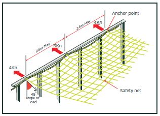
Figure 11: Attaching safety nets to timber structures

Eaves bagging

Where anchor points are widely spaced (see section 4.4 Anchor points), the safety net’s edge may pull in or ‘waist’, leaving a gap that a person could fall through. If waisting occurs, make an ‘eaves bag’ by folding approximately 2.0 metres of net back on itself and stitching the sides together to create a bag around 1.0 metre deep. See Figure 12.

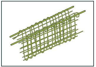
Figure 12: Eaves bagging.

Gaps at net edges:

There should be no gaps between the safety net and the adjacent structure. If unavoidable, gaps of up to 100mm are allowed. If there are obstructions (for example, around columns), a gap of no more than 225 mm is allowed but it must not be able to get any larger.

Joining and over laping:

If more than one net is needed to protect an area, join nets by:
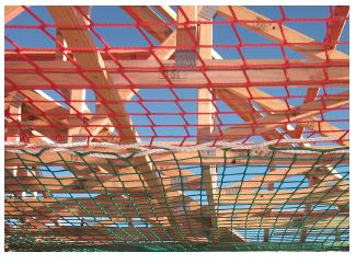
  • lacing, or
  • overlapping.

Safety nets can be laced together using a coupling rope with a minimum 7.5 kN breaking strain (type O or greater as defined in BS EN 1263-1). The coupling rope must pass through every second mesh and around both border ropes. Tie the ends off at the corners. The completed lacing should give a join with gaps no more than 100mm.

Figure 13: Safety nets joined by lacing.

If joining nets by overlapping, the overlap must be at least 2.0 meters (or 20 meshes) wide, measured at the narrowest point for the entire length of the overlap. Nets that follow the slope of the roof should be installed with the upper net overlapping the lower net (referred to as ‘tiling’) so that if a person falls, they will not roll down the pitch and off the open end.

HANDOVER DOCUMENTATION

Once installed, the installer must inspect the safety net to make sure it is correctly installed and fit for purpose. They must then give handover documentation to the main contractor or site supervisor that includes:

  • confirmation that all safety net components comply with BS EN 1263: parts 1 or equivalent
  • confirmation that the safety net was installed in accordance with BS 8411 and BS EN 1263-2 or equivalent
  • a description of the area being ‘handed over’
  • evidence that the safety nets were tested within the past 12 months.

An instruction manual for the nets including information on:

  1. installation, use and dismantling
  2. storage, care and inspection
  3. dates for testing test meshes
  4. conditions for removing safety nets from service
  5.  hazards (such as heat, chemicals, etc)
  6. written instructions on rescue, inspection and debris removal procedures
  7. the name of the person who inspected the net, the handover date, and the signature of the person receiving the handover documentation.

The main contractor or site supervisor must keep the documentation on site for the duration of the construction project.

The safety net system should have a label with the:

  • installer’s name
  • handover date
  • description and area of net
  • net serial or ID numbers
  • clearance distance needed under the nets.

If there is no handover documentation, you should regard the nets as unsuitable for use. Do not carry out work above the nets until the installer provides documentation.

DISMANTLING (STRIKING):

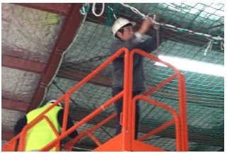
Dismantling (striking) safety nets is the reverse process to installation. Safety nets should only be dismantled by trained installers who can identify and mark net damage.

Plan the dismantling process during the net installation planning stage, to recover the nets safely and intact. Do not drop nets to the ground in an uncontrolled way during dismantling, as damaged nets may not be able to be re-used.

INSPECTIONS

Visual inspections of the safety nets must be carried out regularly by a competent person. An inspection regime is given in Table 3. Records of all inspections must be kept on site.

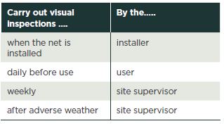
Table 3: Frequency of net inspections.

Visual inspections include checking for:

  • incorrect installation
  • mesh abrasion
  • cuts or nicks in mesh
  • heat or friction damage to mesh
  • stitching damage
  • damaged or deformed fittings
  • dirt or debris in the net
  • defects in knots (if knotted mesh)
  • UV degradation (although generally not seen with visual inspection). If a net does not pass the visual inspection, do not use it. Either remove and repair it, or take it out of service permanently.

TESTING FOR UV DETERIORATION:

Test safety nets at least every 12 months to determine the amount of UV deterioration and to make sure the manufacturer’s minimum energy absorption capacity will be maintained for the next 12 months.

Test meshes ) are attached to the safety net and removed one at a time for annual testing. Test meshes must remain attached to the net until needed for testing. Do not use test meshes for any other purpose.

Nets more than 12 months old must have a current test tag or label attached to the net to confirm the net met the manufacturer’s energy absorption capacity requirements at the most recent testing. Keep the corresponding certificate with details on site. The test tag and certificate must not expire while the net is in use. Test methods for UV deterioration are described in BS EN 1263-1: clause 7.7.

DEBRIS IN THE NET

Safety nets catch a falling person, but they will also catch falling debris. Debris can damage the net, and if left in the net is a hazard because it might:

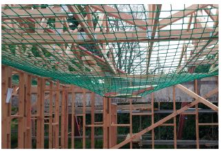
  • injure a falling person
  • cause the net to overload and deflect excessively
  • Increase the net sag and fall distance.

When debris falls onto a safety net, immediately stop work above and below the net. Remove the debris, and have the net checked for damage by a competent person before work continues.

Recommends one person on site is responsible for keeping safety nets free of debris.

Note: Snow on the safety net can overload the net and cause excessive deflection.

NET CARE

Do not damage nets during handling and storage. Damage may occur from:

  • prolonged UV exposure
  • sharp objects
  • abrasion
  • sparks or exposure to heat from welding, grinding or burning
  • adverse weather such as strong winds
  • Significant load or impact.

When handling nets during rigging or striking:

  • do not drag nets across the ground
  • Avoid contact with sharp edges.

When installing nets, do not:

  • stack material onto the net
  • let debris accumulate in the net
  • Allow people to jump or throw objects into the net.

REPAIRING SAFETY NETS AND ROPES

Safety nets must be repaired by a competent person (i.e. someone who has completed a recognized training course within the past 5 years). Nets should preferably be repaired in a controlled environment, away from the site. Repairs must be made using new material that is similar to the net mesh cord and recommended for use by the manufacturer. Cable ties must not be used as a net repair, although they may be used to hold a patch in place before stitching or to tie up the loose ends of a patch.

A label showing the repairer and date of repair must be fixed to the net next to the manufacturer’s label. The repairs must also be recorded and another handover certificate confirming that the safety net remains fit for purpose, should be given to the main contractor or site supervisor.

Border rope repairs must be made using rope with at least 30kN tensile strength. Repairs may be spliced or machine sewn but must not be knotted. Repairs to the net selvage should maintain the original strength of the net.Damaged tie ropes should not be used.

C-Ring and other proprietary repair systems may only be used on safety net systems if they have been approved by the manufacturer as suitable for that net.

REPAIRING A KNOT LESS SAFETY NET

When multiple meshes of a knot less net are damaged, the net should be repaired using new patch material that has been approved by the manufacturer as being suitable for their net, and which complies with BS EN 1263-1.The repair should overlap the entire area that is damaged by at least one mesh. A patch may be laced to the safety net using lacing repair twine to attach all meshes (both the inside and perimeter meshes). Alternatively cable ties may be used to attach the inside meshes of the patch but perimeter meshes must be laced using repair twine.

Single mesh repairs should extend at least one square past the damage, and the repair twine must cross the damaged hole twice. Repairs should not overlap. Repair twine should be at least 3mm thick and double knotted on either side of each node should not overlap. Repair twine should be at least 3mm thick and double knotted on either side of each node.

STORING SAFETY NETS

Store safety nets:

  • undercover
  • in dry conditions
  • protected from UV
  • Away from heat sources and materials or substances that could cause damage, like acids, dyes, solvents and oil. If a safety net has been stored for more than 12 months, it must be inspected and tested for UV deterioration before being re-used.

Click the below image to download the safety net documents

 hand-over-check-sheet

 safe-use-of-safety-nets

 visuval-inspcetion-check-sheet

Aerial Lift Safety

Aerial Lift safety

Overview:

Aerial lifts are commonly used in construction, inspection, athletic events and repair services to lift University employees to an elevated work position. Proper operation and use of aerial lifts can make completion of tasks at elevation, safer and more efficient. However, unsafe use, operation and aerial lift work practices can result in serious injury. This program has been developed due to the hazards associated with improper use and the concern for the safety of individuals in and around this type of equipment. In addition, this program outlines general, operating, maintenance, inspection and training requirements governing safe aerial lift use.

Operate Aerial Lifts / Elevating Work Platforms must:

1. Select and then purchase or rent appropriate equipment for job tasks based upon an work environment and job-task hazard analysis,

2. Train and license personnel who operate their specific type of owned / rented equipment,

3. Conduct documented safety inspections and preventive maintenance of the equipment,

4. Assure operators adhere to specific safe-work practices whenever using these types of powered industrial equipment,

Definitions:

Aerial Device:  Any vehicle mounted or a self propelled device that is telescoping extensible, articulating, or both, and is primarily designed to position personnel.

AL / EWP: Acronym for “Aerial Lift/Elevating Work Platform”

Boom: An elevating member, the lower end of which is so attached to a rotating or non-rotating base that permits elevation of the free end in the vertical plane.

Counter Weight: The rear section or area of the lift which is usually made of solid steel, and/or combination of steel and the weight of the battery on electric lifts, that counter balances the boom leverage and basket load.

Data Plate: Manufacturer‟s equipment specification and information data, which includes basket load rating/lift capacity, lift heights, vehicle weight, and vehicle attachments. This plate is required to be affixed to all Aerial Lift Equipment by regulatory code. This is the vehicle operator‟s primary source of basic information about their vehicle for safe-work and use planning.

Emergency Lowering Means: Any elevating work platform equipped with a powered elevating assembly, and having a platform height exceeding 60 inches, must be supplied with safe means of lowering the basket or platform during an emergency or malfunction.

Fall Protection: An approved full-body safety harness with lanyard is to be worn at all times and attached to a secure anchor point when drivers or personnel are using a boom-type lift or vehicle mounted lift. Fall protection must also be worn when using scissor lifts on uneven surfaces or near locations with tip-over hazards.

Guard Rails: Railing around the perimeter of the work platform. This railing consists of a top rail between 39” – 45” with a mid-rail. Units with the top rail less than 39” must have fall protection in use to operate.

Lower Controls: Operating controls located on the base of the unit which can be switched to override the basket or platform control during an emergency.

Mast: Part of the lifting mechanism to which the hydraulic lift cylinder or worm drive is attached that supports the basket as it is lifted up and down.

Out Riggers: Extendable legs that are either manually set in place or, in some cases, hydraulically extended to give added stability to the unit base.

Platform: Any personnel carrying device (bucket, basket, cage, stand, tub, or equivalent) which is a component of an aerial device.

Upper Controls: Operating controls located on the basket or work platform of the unit. These controls can only be overridden with the operator‟s permission or in case of an emergency.

Requirements:

  • OSHA Standard 29CFR 1910.68 (Powered Platforms, Man lifts, and Vehicle-Mounted Work Platform)
  • OSHA Standard 29CFR 1926.453 (Aerial Lifts)
  • ANSI/SIA A92.6 – 2006 (Self-Propelled Elevated Work Platforms)

Types of Aerial Lift/Elevated Work Platforms

Articulating Boom Lift :

An aerial device with two or more hinged boom sections.

An articulating boom lift is a type of crane that uses hydraulic cylinders to rise and lower and allows a driver to maneuver the boom in any given direction directly from the work platform without lowering the basket. The articulating boom lift is specifically made with at least two boom sections that are hinged and it unhinges at certain points, this makes reaching higher elevations easier.

Articulating boom lifts typically operate with an electric motor or internal combustion as their powers source. It can not only rotate 360 degrees, but also access spots higher than most straight or telescoping boom lifts. They are narrow enough to be maneuvered easily through aisles and crowded work areas and are often found being used in construction, landscaping and plant maintenance.

Note: Fall Protection is required when operating this Lift.

Elevating Work Platform :

A device designed to elevate a platform in a substantially vertical axis. This device is stationary once setup and cannot be moved. Aerial or Personnel lift is an aerial lift that combines the portability of a ladder with the stability of an aerial work platform.

Simple to set up and easy to roll through doorways with a rigid vertical mast and leveling jack that offer stability for the user, the vertical mast raises the work platform to the desired height. Reaching heights of 47 feet and lifting up to 300 lbs, these personnel lifts are more stable than a ladder. It is ideal for indoor use and is suitable for fragile surfaces.

Note: Fall Protection is not required when operating this equipment, but is highly recommended.

Extensible Boom Platform :

An aerial device (except ladders) with an extensible boom. Telescopic booms with personnel platform attachments are considered to be extensible boom platforms. If you are looking for a boom lift with an extended reach capability then a telescopic boom lift is right for you.

Operable from the work platform, even when extended, some telescopic boom lifts are equipped with a jib that provides extra reach and range. Reaching up to 140′ and offering a greater horizontal outreach than any other type of aerial platform, these boom lifts are often used in construction and industrial applications such as road building, bridge work, painting, and landscaping.

Note: Fall Protection is required when operating this equipment.

Scissor Lift :

A device designed to elevate a platform in a substantially vertical axis. This device can also be driven by an operator inside the work platform and is generally designed to carry more than one person.

Also known as a table lift, a scissor lift is an industrial lift that has been modified for retail and wholesale setting. Powered by hydraulics, diesel or an electric motor, this lift will reach anywhere from 21 to 62 feet. It is basically a platform with wheels that acts like a forklift.Portable and effective, this is a lift is useful for completing tasks which require speed and mobility.

The scissor lift is unique in that it doesn’t use a straight support to raise workers into the air, instead, the scissor lift platform raises when the linked, folding supports underneath it draw together, stretching it upward. The scissor lift’s design keeps it from traveling with a constant speed, instead traveling faster in the middle of its climb and slower as it elevates. It can be seen in nearly all manufacturing and production workplaces, including construction, assembly, and vehicle repair.

Note: Fall Protection is not required when operating this Lift, but is highly recommended.

Trailer Mounted Lift :

A device that can be towed by a vehicle to a work site, then un-hitched. These units have extendable or folding outriggers to give stability while being operated. These are compact cranes that can lift up to 30,000 lbs. Designed for both indoor and outdoor job sites, these lifts feature telescoping booms and a load deck for material handling.

They are made for the work place and are self propelled, usually capable of picking up a load and traveling with it. The crane is equipped with a flat deck that is designed to be used as a carrying surface they are perfect for lifting applications requiring a compact, low-profile crane that will clear overhead obstructions and maneuver in tight spaces.

Note: Fall Protection is required when operating this Lift.

Vehicle Mounted Lift :

These devices typically have a Bucket in place of a basket, which is designed for one person. Vehicle must have the brakes set, wheels chocked, and outriggers in place while operating this device. Also  Frequently used by contractors due to their lightweight structure and maneuverability, they are ideal for congested job sites.

As the name states, tow able boom lifts are tow able, easily transportable and ready to use in minutes. Easy to maintain due to having less parts,they are easy to break down. Most have an articulating boom, but some models have a telescopic arm. They are light weight enough to use on lawns, slate, or gymnasium floors and are perfect for home renovations and property management needs.

Note: Fall Protection is required when operating this Lift.

Operating Procedures / Hazard Identification and Controls:

Prior to operation at the beginning of each work-shift, Operators must review and assess the following equipment/work area conditions:

1. Review work area for hazards, and remove/control them prior to operation.

2. Always conduct an environmental hazard assessment prior to selecting/using AL/EWP equipment.

3. Only use AL/EWP equipment designed to safely work in the work-area conditions observed.

4. Review operating instructions, warnings, and precautions for the types of AL/EWP being operated.

5. Prior to operation at the beginning of the work-shift, inspect and document the equipment‟s proper function of controls and instrumentation. Do they operate correctly?

6. Inspect engine or motor operation.

7. Inspect steering and maneuvering.

8. Familiarize yourself with visibility.

9. Inspect basket or platform capacity and equipment stability.

10. Complete and document the inspection process using the appropriate inspection form (in “Attachments”).

11. Check fuel and/or charging of batteries, and refuel/recharge as needed.

12. Review and understand equipment operating limitations.

13. Review other operating instructions, warnings, or precautions listed in the operator’s manual for the types of AL/EWP that you will operate.

14. Alert all persons in the work area of intended work activities and hazards.

15. Always face the direction of travel.

16. Don‟t travel horizontally with the platform elevated or extended.

17. Don‟t exceed the basket or platform capacity.

18. Position equipment on a firm level surface and minimize blocks or ramps for leveling the AL/EWP equipment.

19. Always set outriggers prior to use if the AL/EWP is equipped with them.

20. Wear proper safety harnesses and only tie-off to the work platform‟s fall protection tie-off point. (Refer to “Types of Lifts” and the Inspection Forms in the “Attachments” to determine if safety harnesses are required to be worn.)

21. “Barrier off” the lift swing work-area below the AL/EWP equipment‟s work zone.

22. Don‟t climb on guardrails,climb on ladders or stand on other items when working on the platform.

23. Practices good housekeeping when working in and around the platform.

24. Never drop or throw objects to or from the work platform.

25. Always look below platform and confirm it‟s safe to lower the equipment before lowering theequipment.

26. Never lean the platform on or against structures.

27. Never use the boom to push against something, or try and pull the AL / EWP equipment along in a horizontal direction.

Responsibilities:

  • Must implement and administer the Aerial Lift Safety program.
  • Review the Aerial Lift Safety program annually for compliance and effectiveness.
  • Verify that all employees who operate or work near aerial lifts are properly trained.
  • Maintain written records of operator training on each model of aerial lift and the name of the trainer.
  • Maintain written records of all inspections performed by the aerial lift owner, including the date any problems found, the date when fixed, and the name of the person performing the repairs.
  • Maintain written records of the name and purchaser of each aerial lift.
  • Make recommendations for revisions if necessary.
  • Establish expected operating conditions for aerial lift and send to OHS to review prior to operation

Supervisors:

  • Coordinate employee training, and certify that all operators receive annual training including, but not limited to, the items listed in Section 8.0 of this document.
  • Ensure that only trained and qualified individuals use aerial lifts.
  • Verify employee compliance with the principles and practices outlined in the Aerial Lift Safety Program.
  • Provide specific operational training for each aerial lift.
  • Observe the operation of aerial lifts, and correct unsafe practices.

Operators:

  • Read the Aerial Lift Safety Program.
  • Complete the Daily Pre-Use Inspection Checklist before operating any aerial lift.
  • At least annually review the procedures outlined in Section 6.0 of this document.
  • Observe the operation of the aerial lift, and report unsafe practices to your supervisor.

Occupational Health and Safety Coordinator:

  • Annually review and update the Aerial Lift Safety Program as necessary.
  • Provide orientation and initial training as requested by university departments and/or contractors.
  • Provide the general safety training requirements for program.
  • Monitor the effectiveness of program by receipt of copies of inspection checklists.
  • Evaluate designated areas for aerial lift use.
  • Define appropriate eyewash facilities for battery changing/charging areas.
  • Observe the operation of aerial lifts, and report unsafe practices to the appropriate supervisor.

Aerial Lift Procedures:

Pre-Use Inspection:

  • Prior to the operation of any aerial lift the Pre-Use Inspection Checklist found in bottom of attachment  must be completed. This applies at the beginning of every work period, and whenever a new equipment operator takes control of the aerial lift.
  • Any safety defects (such as hydraulic fluid leaks; defective brakes, steering, lights, or horn; and/or missing fire extinguisher, lights, seat belt, or back-up alarm) must be reported for immediate repair. They must also be locked and tagged, and taken out of service.

General Safe Work Practices:

  • Operators shall not wear any loose clothing or any accessory that can catch in moving parts.
  • Before machine is started, the operator must walk completely around the machine to ensure everyone and everything is clear of the machine.
  • Articulating boom and extendable boom platforms, primarily designed as personnel carriers, shall have both platform (upper) and lower controls. Upper controls shall be in or beside the platform within easy reach of the operator. Lower controls shall provide for overriding the upper controls. Controls shall be plainly marked as to their function. Lower level controls shall not be operated unless permission has been obtained from the employee in the lift, except in case of emergency.
  • Modifications and additions that may affect the capacity or safe operation of an aerial/scissor lift are strictly prohibited without the manufacturer’s written approval. Capacity, operation, and maintenance instruction markings will be changed as necessary if the manufacturer approves a modification.
  • The insulated portion (if applicable) of an aerial / scissor lift shall not be altered in any manner that might reduce its insulating value.
  • Any signs, plates, or decals which are missing or illegible must be replaced.
  • If the aerial / scissor lift becomes disabled, a “out of service” tag or equivalent shall be attached to the controls inside the platform in a conspicuous location.
  • Aerial/scissor lift devices with noted, reported deficiencies shall not be operated until repairs are made and equipment is authorized for use.
  • Operators must report all accidents, regardless of fault and severity, to their Supervisor.

Safe Work Practices Before Operation:

1. Consideration shall be given to the amount of wind. Follow the manufacturer’s instruction regarding operation in windy conditions. As a general rule aerial lifts shall not be operated in winds exceeding 25mph although this can vary depending on the model of equipment.

  • At 20mph wind speeds or anticipated gusts, lifts will be lowered to a maximum height of 20 feet.
  • At 25mph wind speeds or anticipated gusts, lifts will be grounded.
  • If at any time, video personnel/staff feels unsafe in lifts, they may make decision to ground the lifts and cease with videotaping games or practices…no questions asked.

2. Guardrails must be installed and access gates or openings must be closed before raising the platform.

3. Boom and platform load limits specified by the manufacturer shall not be exceeded.

4. Before moving an aerial lift for travel, the boom(s) shall be inspected to see that it is properly cradled and outriggers are in stowed position (if equipped).

5. Consideration shall be given to the protection of bystanders via barricading, having another employee keep bystanders at a safe distance or by other means.

6. Aerial lifts shall not be operated from trucks, scaffolds, or similar equipment.

Safe Operation During Operation:

1. Attention shall be given towards the direction of travel, clearances above, below and on all sides.

2. Employees shall not sit or climb on the guardrails of the aerial lift.

3. Planks, ladders or other devices shall not be used on the work platform.

4. An aerial lift shall not be moved when the boom is elevated in a working position with employees in the basket.

5. Aerial lift shall not be placed against another object to steady the elevated platform.

6. Aerial lift shall not be used as a crane or other lifting device.

7. Aerial lift devices shall not be operated on grades, side slopes or ramps that exceed the manufacturer’s recommendations.

8. The brakes shall be set and outriggers, when used, shall be positioned on pads or a solid surface.

9. Speed of aerial lift devices shall be limited according to the conditions of the ground surface, congestion, visibility, slope, location of personnel and other factors that may cause hazards to other nearby personnel.

10. Stunt driving and horseplay shall not be permitted.

11. Booms and elevated platform devices shall not be positioned in an attempt to jack the wheels off the ground.

12. The area surrounding the elevated platform shall be cleared of personnel and equipment prior to lowering the elevated platform.

13. All equipment must be secured on the inside of the aerial lift.

14. Operators are to call for assistance if the platform or any part of the machine becomes entangled.

Safe Work Practices After Operation:

  • Safe shutdown shall be achieved by utilizing a suitable parking area, placing the platform in the stowed position, placing controls in neutral, idling engine for gradual cooling, turning off electrical power, and taking the necessary steps to prevent unauthorized use.
  • Aerial lifts shall be shut off prior to fueling. Fueling must be completed in well ventilated areas free of flames, sparks or other hazards which may cause fires or explosions.

Changing and Charging Batteries:

1. Battery charging installations must be located in areas designated for that purpose

2. Facilities must provided for: flushing and neutralizing spilled electrolyte, fire protection, protection of charging apparatus from damage by trucks, adequate ventilation for dispersal of fumes from gassing batteries.

3. Precautions must be taken to prevent open flames, sparks, or electric arcs in battery charging areas.

4. Employees charging and changing batteries shall be authorized to do the work, trained in the proper handling, and required to wear protective clothing, including face shields, long sleeves, rubber boots, aprons, and gloves.

Maintenance:

1. Any aerial lift not in safe operating condition must be removed from service. Authorized personnel must make all repairs.

2. Repairs to the fuel and ignition systems of aerial lifts that involve fire hazards must be conducted only in locations designated for such repairs.

3. Aerial lifts in need of repairs to the electrical system must have the battery disconnected before such repairs.

4. Only use replacement parts that are currently recommended by the manufacturer.

Training Requirements:

Employees who are authorized to operate aerial lifts must receive training prior to engaging in their duties, and at least every three (3) years thereafter. The training is to ensure that the Aerial Lift Safety Program is understood. The supervisor will also ensure that authorized aerial lift operators have acquired the necessary practical skills required for safe operation. Training is offered by Occupational Health and Safety, Rental Company and the department in possession of the lift.The department along with the rental company will perform an operational training with each employee to determine if operators have the knowledge, training, and skills necessary to use the aerial lift. Operational training will consist of a combination of general safety instruction, practical/operational training (demonstrations performed by the trainer, and practical exercises performed by the trainee), and evaluation of the operator’s performance in the workplace. All operational training must be conducted under close supervision.

Initial Training:

1. Receive instruction on the intended purpose and function of each control.

2. Prior to operating any Aerial Lift the trainee will read and understand the manufacturer’s operating instruction(s) and aerial lift procedures (Responsibilities), or receive training by a qualified person on the contents of the manufacturer’s operating instruction(s) and users safety rules.

3. Be informed of the Aerial Lift operating limitations and restrictions as defined by the manufacturer.

4. Understand by reading or having a qualified person explain all decals, warnings, and instructions displayed on the Aerial Lift.

5. During operational training, trainees may operate a aerial lift only under the direct supervision of authorized trainers, and where such operation does not endanger the trainee or other employees.

6. All training and evaluation must be completed before an operator is permitted to use an aerial lift without continual and close supervision.

Annual Training:

Must include at least the following

  • Review of the Aerial Lift Inspection & Maintenance Record
  • Review of Section Responsibilities – Procedures.
  • Updated information on new equipment.
  • Review of company written program.

Training Records:

Each department must maintain a record of all individual training, including:

  • Subject of training.
  • Date of training.
  • Name of individual trained.
  • Name of supervisor or Occupational Health and Safety person providing the training.
  • Training records must maintained by the department for a minimum of 3 years.

Operator Training / Licensing Procedures:

Each Operator must successfully complete Operator Safety Training prior to operating AL/EWP equipment on property. Operators may only use the AL/EWP equipment type they have been trained and licensed to operate, or when under the direct supervision of persons who have the knowledge, training and experience to train operators and evaluate their competence “in the field”. Training is conducted in a location where such AL/EWP equipment operation does not endanger property, the trainee, or others. Departments must arrange for their personnel to be licensed by EH&S to operate AL/EWP equipment.

EH&S ensures that each AL/EWP operator is competent to operate AL/EWP equipment safely and in compliance with OSHA requirements, as demonstrated by the successful completion of the training and evaluation specified below. Training consists of a combination of written, classroom, followed by hands-on “field” training and documented testing that‟s specific to the AL / EWP equipment.

Written / Classroom Training:

Written / classroom training includes familiarization with equipment types and components, hazard assessment and mitigation, equipment inspection requirements, and other requirements of this program. Upon successful completion of classroom training, the trainee then takes hands-on training in the field.

Program Evaluation:

The aerial lift program shall be evaluated on an annual basis utilizing the protocols set forth by Occupational Health and Safety. The evaluation team will consist of a department representative and a designee from Occupational Health and Safety. Occupational Health and Safety will define the scope of the evaluation. The final report will be developed by the department representative and OHS utilizing the information received during the evaluation. The deficiencies determined in the report will be documented and corrective action plans will be developed.

Ladder

Ladder

Ladders are used when employees need to move up or down between two different levels. Slips, trips, and falls are significant contributors to accidents. Slips, trips, and falls can occur when wrong ladder selection is made and when improper climbing techniques and/or defective ladders are used.

Appropriate ladders must be used for the corresponding job and defective ladders will not be used. When hazards exist that cannot be eliminated, then engineering practices, administrative practices, safe work practices, Personal Protective Equipment (PPE), and proper training regarding ladders must be implemented.

Basic Ladder Safety Rules:

  • All wood parts must be free from sharp edges and splinters; sound and free from accepted visual inspection from shake, wane, compression failures, decay, or other irregularities.
  • Ladders must be maintained in good condition at all times, the joint between the steps and side rails must be tight, all hardware and fittings securely attached, and the movable parts shall operate freely without binding or undue play.
  • Metal bearings of locks, wheels, pulleys, etc., shall be frequently lubricated.
  • Ladders must be inspected frequently and those which have developed defects must be withdrawn from service for repair or destruction and tagged or marked as “Dangerous, Do Not Use.”
  • Ladders with broken or missing steps, rungs, or cleats, broken side rails, or other faulty equipment shall not be used; improvised repairs are not allowed.

Step ladder – a self-supporting portable ladder, nonadjustable in length, having flat steps and a hinged back. Its size is designated by the overall length of the ladder measured along the front edge of the side rails.

Single ladder – a non-self-supporting portable ladder, nonadjustable in length, consisting of but one section. Its size is designated by the overall length of the side rail.

Extension ladder – a non-self-supporting portable ladder adjustable in length. It consists of two or more sections traveling in guides or brackets so arranged as to permit length adjustment. Its size is designated by the sum of the lengths of the sections measured along the side rails.

Sectional ladder – a non-self-supporting portable ladder, nonadjustable in length, consisting of two or more sections of ladder so constructed that the sections may be combined to function as a single ladder. Its size is designated by the overall length of the assembled sections.

Trestle ladder – a self-supporting portable ladder, nonadjustable in length, consisting of two sections hinged at the top to form equal angles with the base. The size is designated by the length of the side rails measured along the front edge.

Extension trestle ladder  – a self-supporting portable ladder, adjustable in length, consisting of a trestle ladder base and a vertically adjustable single ladder, with suitable means for locking the ladders together. The size is designated by the length of the trestle ladder base.

Special-purpose ladder – a portable ladder which represents either a modification or a combination of design or construction features in one of the general-purpose types of ladders previously defined, in order to adapt the ladder to special or specific uses.

Trolley ladder – a semi-fixed ladder, nonadjustable in length, supported by attachments to an overhead track, the plane of the ladder being at right angles to the plane of motion.

Side-rolling ladder – a semi-fixed ladder, nonadjustable in length, supported by attachments to a guide rail, which is generally fastened to shelving, the plane of the ladder being also its plane of motion. Ladders must not be used in a horizontal position as platforms, runways, or scaffolds. Place portable ladders so that the side rails have a secure footing. The top rest for portable rung and cleat ladders must be reasonably rigid and shall have ample strength to support the applied force.

Safe Ladder Use:

Employees should follow certain rules when placing, ascending, and descending ladders which include:

• Hold on with both hands when going up or down. If material must be handled, raise or lower it with a rope either before going down or after climbing to the desired level.

• Always face the ladder when ascending or descending.

• Never slide down a ladder.

• Be sure shoes are not greasy, muddy, or slippery before climbing.

• Do not climb higher than the third rung from the top on straight or extension ladder, or the second tread from the top on stepladders.

• Carry tools on a tool belt not in the hand.

• Never lean too far to the sides. Keep your belt buckle within the side rails.

• Use a 4 to 1 ratio when leaning a single or extension ladder. (place a 12 foot ladder so that the bottom is 3 feet away from the object the ladder is leaning against.)

• Inspect ladder for defects before using.

• Never use a defective ladder. Tag or mark it so that it will be repaired or destroyed.

• Never splice or lash a short ladder together.

• Never use makeshift ladders, such as cleats fastened across a single rail.

• Be sure that a stepladder is fully open and the metal spreader locked before starting to climb.

• Keep ladders clean and free from dirt and grease.

• Never use ladders during a strong wind except in an emergency and then only when they are securely fastened.

• Never leave placed ladders unattended.

• Never use ladders as guys, braces, or skids, or for any other purpose other than their intended purposes.

• Never attempt to adjust a ladder while a user is standing on the ladder.

• Never jump from a ladder. Always dismount from the bottom rung.

Ladder extension:

  • Place ladders on a firm, level surface and ensure the footing is secure.
  • Erect extension ladders so that the upper section rests on (e.g., in front of) the bottom section. This means the bottom section “faces” a wall or other supporting surface (see figures below).
  • Place the ladder feet so that the horizontal distance between the feet and the top support is 1/4 of the working length of the ladder. The ladder will be leaning at a 75 degree angle from the ground.

Extension ladder

  • Raise and lower ladders from the ground. Ensure that locking ladder hooks are secure before climbing.
  • Erect ladders so that a minimum of 1 m (3 ft) extends above a landing platform. Tie the top at support points.
  • Brace or tie off the ladder near the base. If there is no structure to tie off to, use a stake in the ground.
  • Leave all tie-off devices in place until they must be removed before taking the ladder down.
  • Maintain the minimum overlap of sections as shown on a ladder label. Refer to safety regulations.

Note: When working 3 metres (10 feet) or more above ground, wear a safety belt or harness with the lanyard tied appropriately to the structure.

Extension ladder parts

Avoid when using extension ladders:

  • Do not use ladders near electrical wire.
  • Do not set up or take a ladder down when it is extended.
  • Do not overextend. Maintain minimum overlap of sections.
  • Do not climb higher than the fourth rung from the top of a ladder.
  • Do not use ladders on ice, snow or other slippery surfaces without securing ladders’ feet.
  • Do not extend top section of a ladder from above or by “bouncing” on a ladder.
  • Do not leave ladders unattended.

Climbing a fixed ladder:

  • Wait until the other person has exited before ascending or descending.
  • Use the appropriate safety devices (e.g., restraint belt, traveling fixture).
  • Maintain three-point contact by keeping two hands and one foot, or two feet and one hand on a ladder always.
  • Face ladder and use both hands to grip the rungs firmly.
  • Place feet firmly on each rung.
  • Wear footwear with heels. Ensure that footwear is in good condition.
  • Clean muddy or slippery boot soles before mounting a ladder.
  • Rise or lower tools and materials using a hand-line.

Fixed access ladder

Wear appropriate safety devices

How should you set up the ladder:

  • Place the ladder feet 1/4 of the ladder’s working length (e.g., foot to top support point) away from the base of the structure (e.g., for every 1.2 m (4 ft ) high, the base of the ladder should be out 0.3 m (1 ft); that means one horizontal foot from the support point).
  • Extend the ladder at least 1 m (3 ft) above the landing platform.
  • Place the ladder on a firm, level footing. Use a ladder with slip-resistant feet or secure blocking. Brace or tie the bottom of the ladder.
  • Rest both side rails on the top support and secure ladder to prevent slipping.

What should you know about climbing portable ladders:

  • Check for overhead electrical wires before setting up a ladder.
  • Clear area around base and top of the ladder of debris, tools and other objects.
  • Tie off yourself with a safety harness when working 3 m (10 ft) or more off the ground or when working with both hands.
  • Ensure that only one person is on a single-width ladder. Only one person is allowed on each side of a double-width ladder.
  • Maintain three-point contact by keeping two hands and one foot, or two feet and one hand on the ladder at all times.
  • Grasp the rungs when climbing a ladder, not the side rails. If your foot slips on a ladder, holding onto rungs is easier than holding onto the side rails.

3 Point Contact

  • Wear protective footwear with slip-resistant soles and heels.
  • Ensure that all electrical equipment used during ladder work is in good condition and properly grounded.
  • Rest frequently to avoid arm fatigue and disorientation when the work requires you to look up and reach above your head.
  • Drape your arms over a rung and rest your head against another rung or side rail if you become dizzy or panicky. Climb down slowly.

Proper way to store ladders:

  • Return ladders to storage area after use.
  • Store ladders where they are protected from the weather.
  • Support ladders horizontally on racks. To prevent sagging, support ladders every 2 m (6 ft).
  • Keep ladders clean and free of foreign materials.

Support Ladders

  • Ensure that storage areas are easy to reach.
  • Keep wooden ladders in a well-ventilated location, away from dampness and excessive heat.
  • Avoid long overhangs beyond support points when transporting ladders on vehicles.
  • Pad racks on vehicles with soft material to reduce wear and road shocks.
  • Tie ladders to each support point to reduce damage.
  • Mark ladders which overhang vehicles with a red or orange flag.
  • Grasp ladders near the center when carrying them.
  • Use caution when carrying ladders through passageways, doorways or any place where your view is obstructed.
  • Use a partner to help carry long or heavy ladders.
  • Ensure that you and your partner are on the same side when carrying a ladder. Stay in step. Work out in advance any hand or voice signals to coordinate stopping or changing direction.

Carrying Ladders

Avoid when storing ladders:

  • Do not hang ladders from rails or rungs.
  • Do not store materials on ladders.
  • Do not expose fiberglass ladders to excessive temperatures (above 93°C or 200°F).
  • Do not hold the front of ladders at head level when carrying them.
  • Do not expose plastic-reinforced ladders to excessive sunlight. Ultraviolet light may cause the plastic resins to degrade. If the strength of the ladder is questionable, replace the ladder.

When using a stepladder:

  • Use a stepladder that is about 1 m (3 ft) shorter than the highest point you have to reach. This gives a wider, more stable base and places shelf at a convenient working height.
  • Open the stepladder spreaders and shelf fully.
  • Check stability. Ensure that all ladder feet are on a firm, level and non-slippery surface.
  • Place a stepladder at right angles to the work, with either the front or back of the steps facing the work.
  • Keep the stepladder close to the work.

Lock Spreader

  • Avoid pushing or pulling stepladders from the side. Repeated sideways movement can make ladders wobbly since they are weaker or less stable in those directions.
  • Face the stepladder when climbing up or down. Keep your body centered between side rails. You have climbed too high if your knees are above top of the stepladder or if you cannot maintain a handhold on the ladder.
  • Maintain a firm grip. Use both hands when climbing.

When using a stepladder:

  • Do not overreach. Move a stepladder when needed.
  • Do not “shift” or “walk” a stepladder when standing on it.
  • Do not stand, climb, or sit on the stepladder top or pail shelf.
  • Do not overload. Stepladders are meant for one person.
  • Do not use a stepladder as a brace or as a support for a work platform or plank.

Avoid!

  • Do not climb a stepladder that is leaning against a wall. Use a straight ladder instead.
  • Do not use stepladders on slippery surfaces.
  • Do not use stepladders on soft ground where one leg may sink farther into the ground than others.
  • Do not place stepladders on boxes, unstable bases or on scaffolds to gain additional height.
  • Do not climb the back of a stepladder.
  • Do not push or pull stepladders sideways.
  • Do not use ladders in passageways, doorways, driveways or other locations where a person or vehicle can hit it. Set up suitable barriers or lock doors shut.

Stepladder Components

Click the below link to know more detail about Ladder safety


ladder guidelines 

Ladders portable

Fixed ladders

Ladder – Tool box talk

Ladder safe-Extention